How to use a SW-420 Vibration Sensor
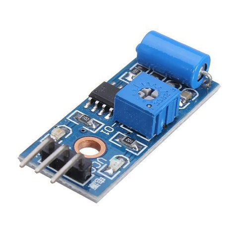
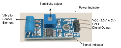
The SW-420 Vibration Sensor Module is a useful module for detecting vibrations over a threshold point and provide digital data, 0 or 1. It uses an LM393 comparator to detect and it can work from 3.3V to 5V.
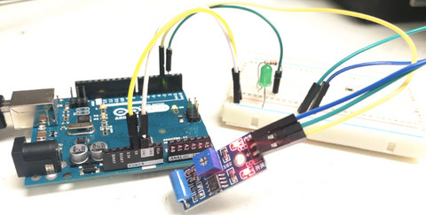
In this article, we'll talk about how to wire and set up the module for operation with an Arduino Board.
Wiring
This module can work from 3.3V to 5V. In this project, we will use 5V to power the module. During normal operation, the sensor provides Logic Low and when the vibration is detected, the sensor provides Logic High.
There are several types of vibration sensors available in the market which can detect the vibration bye sensing acceleration or velocity and could provide an excellent result. However, some of them are too expensive. But, there are a few dedicated and cheap sensors that are able to detect vibrations only, like SW-420, which we are going to use with Arduino Uno. We will work with SW-420 Vibration Sensor Module, the one we carry in our shop.
Parts
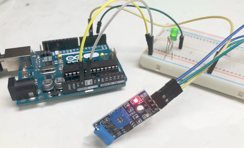
Wiring Guide
- SW-420 GND — Arduino GND Pin
- SW-420 VCC (5V) — Arduino 5V
- SW-420 OUT — Arduino Pin D3
- LED + — Arduino Pin D2
- LED - -- Arduino GND Pin
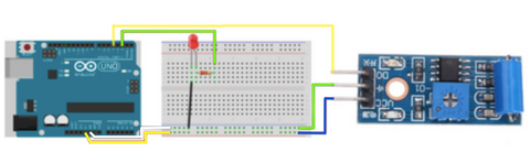
The LED lightbulb is used to indicate if the sensor detects any vibrations. It will flash if there is a vibration, otherwise it will be off.
Programming
The following code is to demonstrate how the vibration sensor works. The LED lightbulb will show us the state of the sensor when it is triggered and when it is not. If you want to skip the steps, you can jump to the Full Code.
Step 1: We will need to define the pins on Arduino Code by variables. From the code below, we defined the vibration sensor to pin 3 and the LED lightbulb to pin 2, as where we have connected previously.
int vibration_sensor = 3;
int LED = 2;
Step 2: We will need two variables to store the conditions: previous and current. So that Arduino can detect if there is any vibration.
int current_condition = 0;
int previous_condition = 0;
Step 3: We will set up the module and the LED lightbulb as input and output so that Arduino knows where to receive data and where to send the signal. From the code below, the vibration sensor is set as an input where it will send the signal to Arduino. The LED lightbulb is set as an output that will receive the data.
void setup() {
  pinMode(vibration_sensor, INPUT);
  pinMode(LED, OUTPUT);
}
Step 4: We will update the "previous condition" as the "current" one (which the current condition was the condition the sensor has just detected). Then, we will use the current condition to read the vibration sensor.
previous_condition = current_condition;
current_condition = digitalRead(vibration_sensor);
Step 5: If the previous condition is the same as the current condition, it means that the sensor did not detect any vibration. And if the previous condition is different from the current condition, it means that the sensor detected a vibration. As the sensor detects vibration, we will set the LED lightbulb to be flashing.
if (previous_condition != current_condition){
    digitalWrite(LED, HIGH);
    delay(500);
    digitalWrite(LED, LOW);
    delay(500);
    digitalWrite(LED, HIGH);
    delay(500);
    digitalWrite(LED, LOW);
    delay(500);
  }
  else{
    digitalWrite(LED, LOW);
  }
Full Code:
int vibration_sensor = A0;
int LED = 9;

int current_condition = 0;
int previous_condition = 0;

void setup() {
  pinMode(vibration_sensor, INPUT);
  pinMode(LED, OUTPUT);
}

void loop() {
  previous_condition = current_condition;
  current_condition = digitalRead(vibration_sensor);

  if (previous_condition != current_condition){
    digitalWrite(LED, HIGH);
    delay(500);
    digitalWrite(LED, LOW);
    delay(500);
    digitalWrite(LED, HIGH);
    delay(500);
    digitalWrite(LED, LOW);
    delay(500);
  }
  else{
    digitalWrite(LED, LOW);
  }

}
Output
When the module is triggered. The LED is flashing.

When the module is not triggered. The LED is not on.