How to use The Rotary Encoder Module
The rotary encoder is a type of position sensor that is used to determine the angular position of a rotating shaft and converts to analog or digital output signals.
In this article, we'll talk about how to wire and set up the module for operation with an Arduino Board.
Wiring
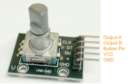
The rotary encoder module operates at 5V and produces an analog or digital output. There are many different types of rotary encoders in the market which are classified by output signals or sensing technology. However, we will be using Rotary Encoder Module, the one we carry in our shop.
Parts
Wiring Guide
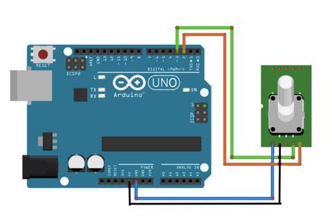
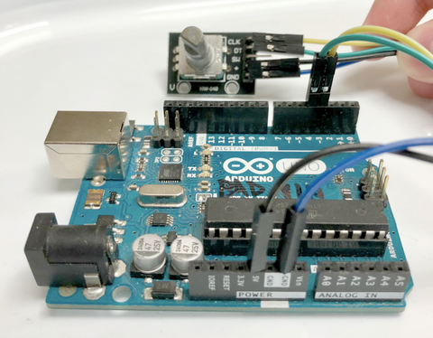
Connect all the pins with male to female jumper wires
Rotary Encoder Module output A -- Arduino D3 pin Rotary Encoder Module output B -- Arduino D4 pin Rotary Encoder Module VCC (5V) -- Arduino 5V pin Rotary Encoder Module GND -- Arduino GND pin


Programming
The following code detects when the encoder is being rotated clockwise or anti-clockwise. If you want to skip the steps, you can jump to the Full Code.
Step 1: We will need to define the pins on Arduino Code by variables. From the code below, we defined the outputA to pin 3 and outputB to pin4 as what we previously connected onto Arduino Uno.
#define outputA 3
#define outputB 4
Step 2: We will need three variables to store the conditions: laststate and state, and counter. So, Arduino knows the state of the encoder when you twist the knob. "last state" is storing the previous state of the encoder (the position or angle) and "state" is storing the current state of the encoder.
int counter = 0;
int laststate;
int state;
Step 3: We will set up both the outputs as input, so Arduino knows it is receiving data and signals from them.
pinMode(outputA, INPUT);
pinMode(outputB, INPUT);
Step 4: We will set up a serial communication between Arduino Board and the encoder so that Arduino can read the state from the encoder outputA.
Serial.begin(9600);
laststate = digitalRead(outputA);
// reads initial state of outputA
Step 5: As we have the value from last state, we will ask Arduino to read the current state of outputA and compare it with the previous state (last state). If the states are not the same, it means a pulse has occurred. Or, if outputB state is different from "state", it means the encoder is turning clockwise. We will also add 1 to the counter as it turns clockwise, and minus 1 to the counter if it turns anti-clockwise.
void loop() {
  state = digitalRead(outputA); // reads current state of outputA
  if (state != laststate){
  //a pulse has occured
    if (digitalRead(outputB) != state){
// the encoder is rotating clockwise
      counter++;
    }
    else{
      counter--;
    }
Step 6: Since Arduino has all the data from the encoder's outputs, Arduino will send out the data onto the Serial Monitor, telling us about the state and position the encoder has rotated to. Lastly, we would update the previous state (last state) from our current data (state).
Serial.print("Position: ");
    Serial.println(counter);
  }
  laststate = state; // update the previous state of outputA
Full Code:
#define outputA 3
#define outputB 4

int counter = 0;
int laststate;
int state;

void setup() {
  pinMode(outputA, INPUT);
  pinMode(outputB, INPUT);

  Serial.begin(9600);
  laststate = digitalRead(outputA); // reads initial state of outputA

}

void loop() {
  state = digitalRead(outputA); // reads current state of outputA
  if (state != laststate){ // a pulse has occured
    if (digitalRead(outputB) != state){
    // the encoder is rotating clockwise
      counter++;
    }
    else{
      counter--;
    }
    Serial.print("Position: ");
    Serial.println(counter);
  }
  laststate = state; // update the previous state of outputA
}
Serial Monitor Output
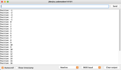
The Serial Monitor outputs the position/coordinate of the rotary encoder. When the value decreases, it means it is rotating anti-clockwise. And vice versa, when the value is increasing, it means it is rotating clockwise.
