How to use The Photocell Module
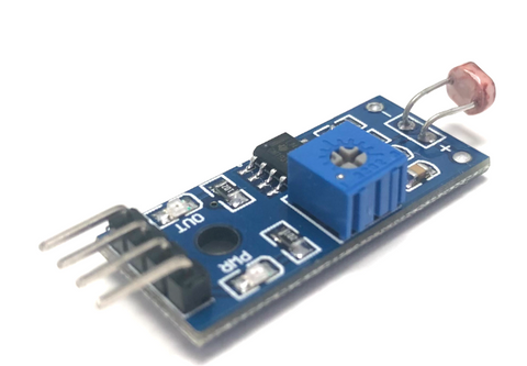
The light sensor is a photoresist, which is also known as a light-dependent resistor or photocell. It is used not only to detect light but also to measure the brightness or illuminance level of the ambient light. It has a wide range of applications, such as measuring the brightness of ambient light and controlling the lights turning on and off.
How it works
The more light the photoresist’s face is exposed to, the smaller its resistance is. Therefore, we know how bright the ambient light is by measuring the photoresistor’s resistance.
In this article, we'll talk about the setup and wiring of the module operating with an Arduino Board. At the end of the tutorial, you will learn how to use the light sensor to control the light turning on and off depending on the illuminance level of the light.
Wiring
The light sensor module operates at 3.3V to 5V, while its analog input pin can convert the voltage (from 0V to 5V) to integer values (between 0 to 1023). There are a few types of light sensor modules in the market where some do not come with a potentiometer for adjusting the sensitivity. We will be using Photocell Module, the one we carry in our shop.
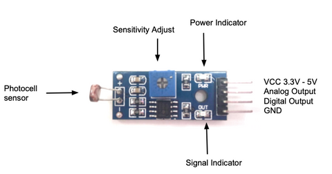
This module consists of 4 pins that allow it to connect to a microcontroller, like Arduino.
- GND: Ground pin to connect the sensor to the ground with the microcontroller
- VCC: Power pin for 3.3V to 5V operation voltage with the microcontroller
- D0: Digital output pin based on a predefined threshold through the potentiometer and the operation voltage of the microcontroller.
- A0: Analog input pin converts the voltage (between 0V and VCC) into integer values (between 0 and 1023), called analog value.
Parts
Wiring Guide
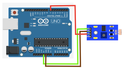
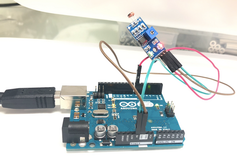
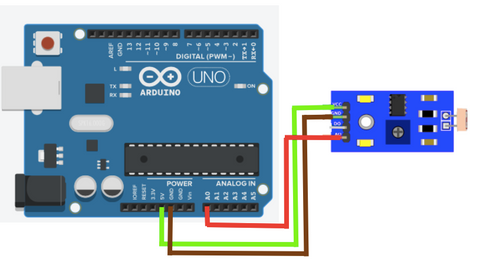
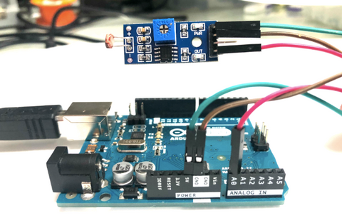
Connect the pins with female to male jumper wires
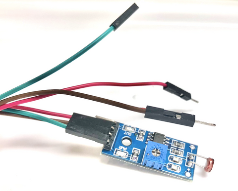
- Light Sensor GND pin -- Arduino GND pin
- Light Sensor VCC pin -- Arduino 5V pin
- Light Sensor D0 pin -- Arduino D7 pin
- Light Sensor A0 pin -- Arduino A0 pin
Connecting for digital outputs
**Connecting for Analog input **

Programming
**We will have 3 different coding projects. If you want to go to a specific one, please click on the title you want. **
-
Detect light level and switch the LED on or off
-
Determine light level
-
Controlling the LED by detecting the light level
Detect light level and switch the LED on or off
We want to turn on the internal LED on Arduino Uno when the brightness level is low on the ambient light.
If you want to skip the steps, you can jump to the Full Code.
Step 1: Define the connection pins.
#define sensor 7
#define internal_LED 13
Step 2: Create a variable to store the digital output from the light sensor.
int state = 0;
Step 3: Set up serial communication between Arduino and light sensor, and set internal led as an output, and sensor as input. This way the sensor will send the signal to Arduino, and Arduino will give out a signal and perform the action on the LED light.
void setup(){
  pinMode(sensor, INPUT);
  pinMode(internal_LED, OUTPUT);
  Serial.begin(9600);
}

**Step 4:** Get digital output from sensor, and print out the data.

```c
void loop(){
  state = digitalRead(sensor);
  Serial.print("State: ");
  Serial.print(state);
Step 5: Determine if the LED should be on or off. The LED will be on if the sensor is HIGH (when the brightness level is low), and the LED will be off if the sensor is LOW (when the brightness level is high).
  if (state == HIGH){
    digitalWrite(internal_LED, HIGH);
    Serial.println(" \t LED ON");
  }
  else{
    digitalWrite(internal_LED, LOW);
    Serial.println("\t LED OFF");
  }
}
Full Code
#define sensor 7
#define internal_LED 13

int state = 0;

void setup(){
  pinMode(sensor, INPUT);
  pinMode(internal_LED, OUTPUT);
  Serial.begin(9600);
}

void loop(){
  state = digitalRead(sensor);
  Serial.print("State: ");
  Serial.print(state);

  if (state == HIGH){
    digitalWrite(internal_LED, HIGH);
    Serial.println(" \t LED ON");
  }
  else{
    digitalWrite(internal_LED, LOW);
    Serial.println("\t LED OFF");
  }
}
Output
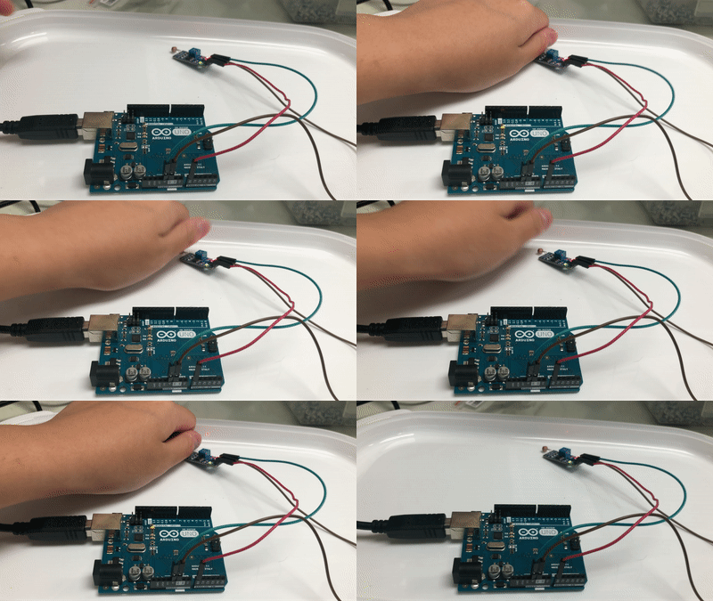
When it is dark enough, the internal LED (The light next to pin 13) will turn on.
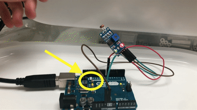
The internal led light will turn on when it is dark. Take a closer look at the light near pin 13 on Arduino.
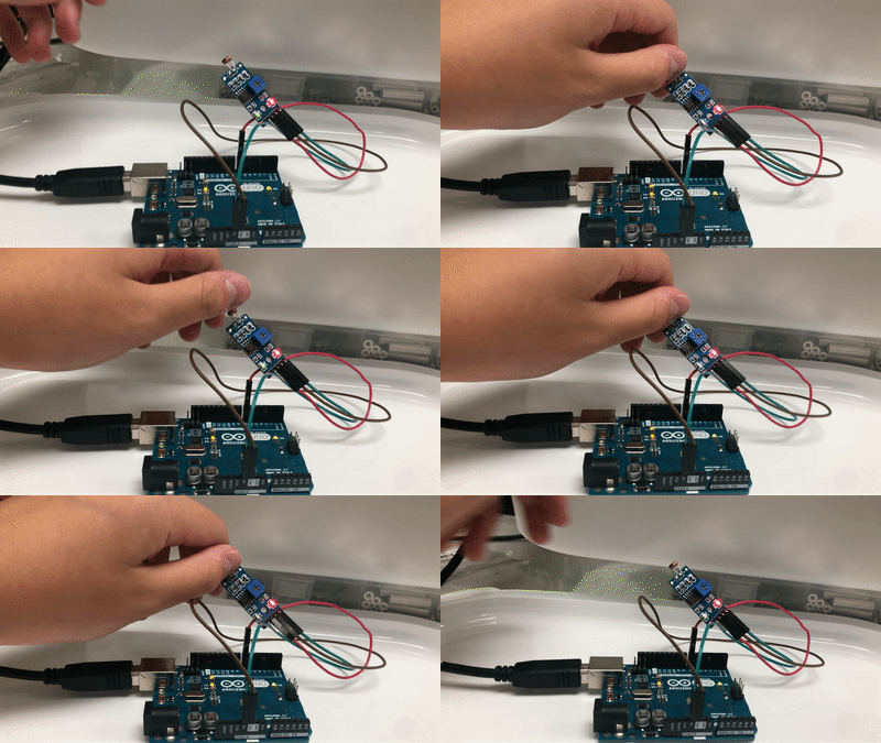
When it is still bright
When it is dark
Determine light level
In the following code, we will read the data from the analog pin and depending on the data, we will know the brightness level of the ambient light around us.
Noted that we are using the analog pin now, instead of the digital pin. Please check this image for the wiring.
If you want to skip the steps,you can jump to the Full Code.
Step 1: Define the connection pin.
#define sensor A0
Step 2: Create a variable for storing analog input data.
int value = 0;
Step 3: Set up serial communication between Arduino and the light sensor, and set the sensor as an input. This way, the sensor will send the signal to Arduino, and Arduino will perform actions from receiving it.
void setup(){
  Serial.begin(9600);
  pinMode(sensor, INPUT);
}
Step 4: Get input value from analog pin.
void loop(){
  value = analogRead(sensor);

  Serial.print("Analog reading: ");
  Serial.print(value);
Step 5: Determine the brightness level of the ambient light around us. (You might want to test out the values yourself)
 if (value < 10){
    Serial.println("\t -- Very Bright");
  }
  else if (value < 200){
    Serial.println("\t -- Bright");
  }
  else if (value < 500){
    Serial.println("\t -- Light");
  }
  else if (value < 800){
    Serial.println("\t -- Dim");
  }
  else{
    Serial.println("\t -- Dark");
  }

  delay(500);
}
Full Code
#define sensor A0

int value = 0;

void setup(){
  Serial.begin(9600);
  pinMode(sensor, INPUT);
}

void loop(){
  value = analogRead(sensor);

  Serial.print("Analog reading: ");
  Serial.print(value);

  if (value < 10){
    Serial.println("\t -- Very Bright");
  }
  else if (value < 200){
    Serial.println("\t -- Bright");
  }
  else if (value < 500){
    Serial.println("\t -- Light");
  }
  else if (value < 800){
    Serial.println("\t -- Dim");
  }
  else{
    Serial.println("\t -- Dark");
  }

  delay(500);
}
Output
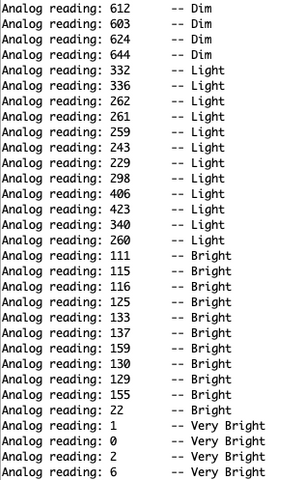
Move around and test it out!
Arduino will tell you the brightness level of the light around you depending on the analog output the sensor produces. The higher the value, the darker the brightness level.
Controlling the LED by detecting the light level
Noted that we are using the analog pin now, instead of the digital pin. Please check this image for the wiring.
In the following code, we will detect the light level and control the light. If the brightness level is on a certain value, it means it is dark enough to turn on the light. Otherwise, the light will be off. If you want to skip the steps, you can jump to the Full Code.
Step 1: Define the connection pins.
#define sensor A0
#define internal_LED 13
Step 2: Create two variables to store analog input and store a value to compare with analog input.
const int analog_threshold = 500;
int value = 0;
Step 3: Set the light sensor as input and the internal led as output. This way, the sensor will send a signal to Arduino, and Arduino will act upon it and send the output signal to the LED.
void setup(){
  pinMode(sensor, INPUT);
  pinMode(internal_LED, OUTPUT);
}
Step 4: Get analog input from sensor.
void loop(){
  value = analogRead(sensor);
Step 5: Compare the input with the value. If the input is less than the value, it means it is still bright. Otherwise, it means it is too dark.

  if (value > analog_threshold){
    digitalWrite(internal_LED, HIGH);
  }
  else{
    digitalWrite(internal_LED, LOW);
  }
}
Full Code
#define sensor A0
#define internal_LED 13

const int analog_threshold = 500;
int value = 0;

void setup(){
  pinMode(sensor, INPUT);
  pinMode(internal_LED, OUTPUT);
}

void loop(){
  value = analogRead(sensor);

  if (value > analog_threshold){
    digitalWrite(internal_LED, HIGH);
  }
  else{
    digitalWrite(internal_LED, LOW);
  }
}
Output
As we cover up the photocell, the brightness level will be lower than the threshold value, which Arduino will turn on the internal led (the light next to pin 13).
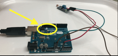
The internal led is next to pin 13 on Arduino. It will turn on and off according to the brightness level.
