How to use The Infrared Sensor Module with Adjustable Reference
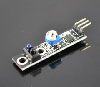
The Infrared Sensor Module (TCRT5000) with Adjustable Reference is a Line Tracking Module. It is an infrared distance module most used for robot applications like a line following robot car, product line decoder and much more. This module can adjust the sensitivity distance from 2cm to 40cm by twisting the potentiometer clockwise and anti-clockwise.
This article will talk about the pinout and wiring of the module operating with an Arduino Board. At the end of the tutorial, you will learn how to build a line decoder to detect objects.
Wiring
The infrared module operates at 3V to 5V DC and produces a digital output. There are two different types of infrared modules in the market where one can produce analog output and the other cannot. We will be using the Infrared Sensor Module (TCRT5000) with Adjustable Reference (the one with no analog output), the one we carry in our shop.
The module consists of 3 output pins that connect the TCRT5000 module to a microcontroller, like Arduino.
- GND: Ground pin to connect the tracking sensor to the ground with the microcontroller
- VCC: Power pin for 3.3V to 5V operation voltage with the microcontroller
- S: Digital output pin based on a predefined threshold through the potentiometer and the operation voltage of the microcontroller.
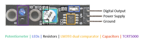
The potentiometer defines a threshold for the digital output pin.
The LED is to indicate the status of the digital pin.
The multiple resistors are to prevent the LED from too high voltages and to operates as voltage dividers.
The LM393 dual comparator is used to compare the signal created by the IR receiver with the redefined value through the potentiometer and to control the LED status that indicates the status of the digital output.
The TCRT5000 reflective IR sensor has two parts: the blue LED is an emission of the infrared radiation, the black part is an infrared receiver, and the daylight is blocked with the black surface.
Parts
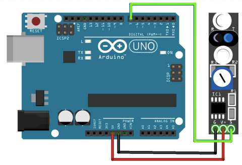
Wiring Guide
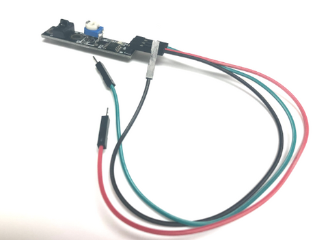
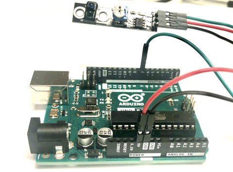
Connect all the pins with female to male jumper wires
- Infrared Sensor Module G -- Arduino GND pin
- Infrared Sensor Module V+ -- Arduino 5V pin
- Infrared Sensor Module S -- Arduino D7 pin
Programming
We want to turn on the internal LED on Arduino Uno when the sensor module detects something in front of it.
If you want to skip the steps, you can jump to the Full Code.
Step 1: Define the connection pin and internal LED.
#define digital_pin 7
#define internal_LED 13
Step 2: Set up the sensor module digital output pin as input and the internal LED as output.
void setup(){
  pinMode(digital_pin, INPUT);
  pinMode(internal_LED, OUTPUT);
}
Step 3: Read digital output from sensor module's digital pin.
void loop(){
  if (digitalRead(digital_pin) == HIGH){
Step 4: If the output is HIGH (when it receives light/detects white colour), the internal LED will be turned off.
 // read digital state of the sensor module
    digitalWrite(internal_LED, LOW); // turn off led
  }
Step 5: If the output is LOW (when it does not receive any light/ detects black colour), the internal LED will be turned on.
else{
    digitalWrite(internal_LED, HIGH); // turn on the led
  }
}
Full Code
#define digital_pin 7
#define internal_LED 13

void setup(){
  pinMode(digital_pin, INPUT);
  pinMode(internal_LED, OUTPUT);
}

void loop(){
  if (digitalRead(digital_pin) == HIGH){
    // read digital state of the sensor module
    digitalWrite(internal_LED, LOW); // turn off led
  }
  else{
    digitalWrite(internal_LED, HIGH); // turn on the led
  }
}
Output
Next to the GND pin, the internal LED light will be turning on or off depending if the sensor detects the colour or light. I am covering the sensor to demonstrate its output. Please use a black-coloured piece of paper to cover it or with an object.