How to use The Infrared Sensor Module
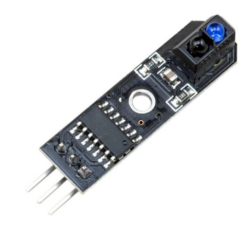
The Infrared Sensor Module (TCRT5000) is a Line Tracking Module. It is an infrared distance module most used for object and obstacle detection, and robot applications like a line following robot car, product line decoder and much more.
This article will talk about the pinout and wiring of the module operating with an Arduino Board. At the end of the tutorial, you will learn how to build a line decoder to detect objects.
Wiring
The infrared module operates at 3V to 5V DC and produces a digital output. There are two different types of infrared modules in the market where one can produce analog output and the other cannot. We will be using the Infrared Sensor Module (TCRT5000) (the one with no analog output), the one we carry in our shop.
The module consists of 3 output pins that connect the TCRT5000 module to a microcontroller, like Arduino.
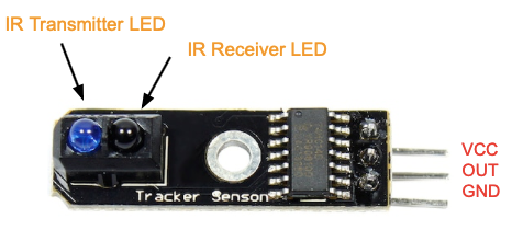
- GND: Ground pin to connect the tracking sensor to the ground with the microcontroller
- VCC: Power pin for 3.3V to 5V operation voltage with the microcontroller
- OUT: Digital output pin based on a predefined threshold through the potentiometer and the operation voltage of the microcontroller.
Parts
- Infrared Sensor Module (TCRT5000)
- Arduino Uno R3
- Jumper wires
- LED lightbulb
- Breadboard
- 220 ohms resistor
- Arduino IDE
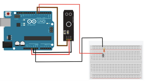
Wiring Guide
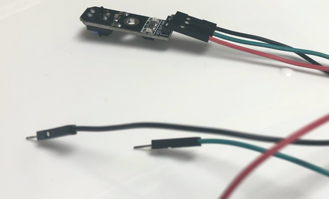
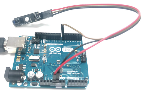
Connect all the pins with female to male jumper wires
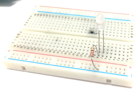
Connect the LED bulb on to the breadboard with a 220 ohms resistor
It does not matter how you put the resistor on to the breadboard as both the legs can be ground or VCC.
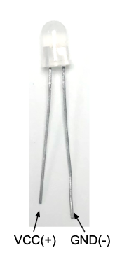
- the longer leg of the LED (GND) -- same row with the resistor
- the shorter leg of the LED (VCC) -- different column with the resistor
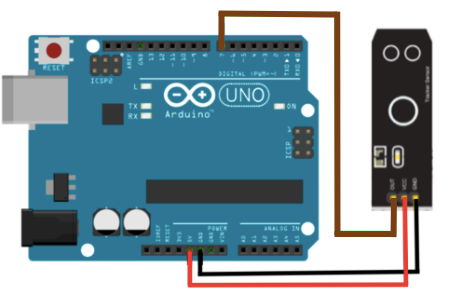
Connect the infrared sensor to Arduino
- Infrared Sensor Module GND -- Arduino GND pin
- Infrared Sensor Module VCC -- Arduino 5V pin
- Infrared Sensor Module OUT -- Arduino D7 pin
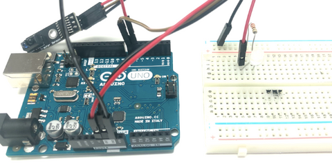
Connect Led to Arduino.
- Breadboard GND rail -- Arduino GND pin
- same row as the led shorter leg (VCC) -- Arduino D6 pin
Programming
We want to read the output from Serial Monitor, so we know what is really happening with the infrared sensor module.
If you want to skip the steps, you can jump to the Full Code.
Step 1: Define the connection pin
#define digital_pin 7
#define led 6
Step 2: Create a variable to store the sensor's output.
int value = 0;
Step 3: Set up serial communication between Arduino and the module and set the digital_pin as an input and the led light as an output.
void setup(){
  Serial.begin(9600);
  pinMode(digital_pin, INPUT);
  pinMode(led, OUTPUT);
}
Step 4: Read the sensor's output.
void loop(){
  value = digitalRead(digital_pin);
Step 5: Print out the sensor's output.
  Serial.print("Digital Reading: ");
  Serial.println(value);
Step 6: The led light will light up according to the status of the sensor.
  if (value == HIGH){
    digitalWrite(led, HIGH);
  }
  else{
    digitalWrite(led, LOW);
  }

}
Full Code
#define digital_pin 7
#define led 6

int value = 0;

void setup(){
  Serial.begin(9600);
  pinMode(digital_pin, INPUT);
  pinMode(led, OUTPUT);
}

void loop(){
  value = digitalRead(digital_pin);
  Serial.print("Digital Reading: ");
  Serial.println(value);
  if (value == HIGH){
    digitalWrite(led, HIGH);
  }
  else{
    digitalWrite(led, LOW);
  }

}
Output
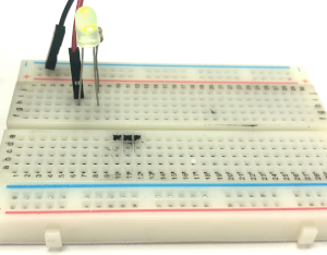
We will cover up the LED with our fingers to demonstrate what it is like when it detects an object in front of it.
When it detects an object
The led light will be turned on
Serial Monitor:

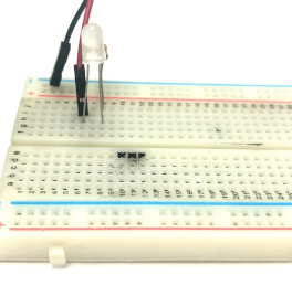
When it does not detect anything
The led will be turned off
Serial Monitor:
