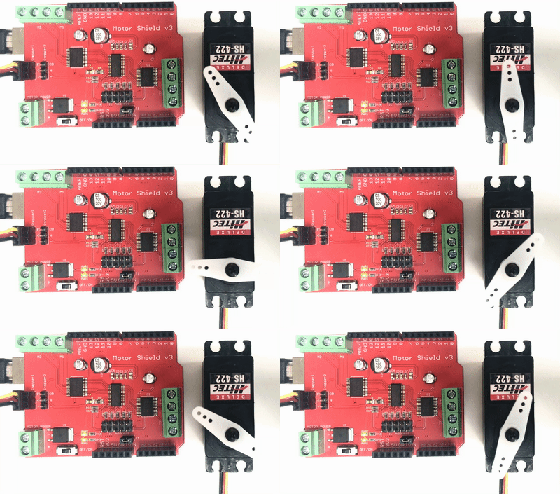
How to use The CAROBOT Motor Shield v3
The CAROBOT Motor Shield allows you to easily control motor direction and speed using an Arduino. By allowing you to simply address Arduino pins, it makes it very simple to incorporate a motor into your project. It also allows you to be able to power a motor with a separate power supply of up to 12v. For all of these reasons, this motor shield is a popular device that is commonly used in projects, such as robot cars, and much more.
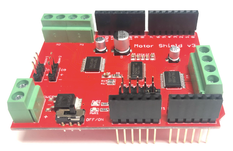
In this article, we will talk about the setup and operation of the CAROBOT Motor shield with Arduino.
Parts
Wiring Guide
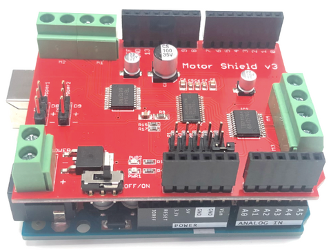
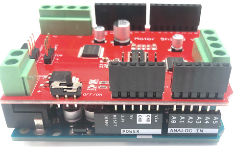
The pins of the motor shield is designed to stack on Arduino Uno as it will only align with it. In order to make it work with other versions of Arduino boards, you will need to use jumper wires to connect the according pins.
All you need to do is to stack the motor shield onto Arduino Uno.
Make sure you match the pins with Arduino Uno before stacking.
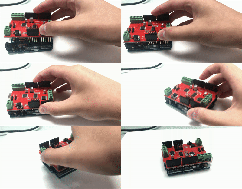
After stacking
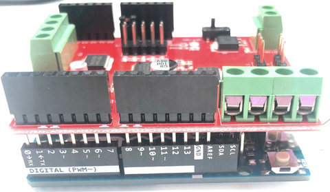
The header pins will not go all the way down in the stackable pins.
| Side view | Top view |
|---|---|
 |  |
 |
Wiring PinOut
The motor shield has 6 channels, which allows for the control of 4 DC motors and 2 stepper motors.
- 2 connections for 5V 'hobby' servos connected to the Arduino's high-resolution dedicated timer
- 4 H-Bridges that can run motors on 4.5V DC to 13.5V DC
There are pins on the Arduino that are always in use by the shield. By addressing these pins, you can select a motor channel to initiate, specify the motor direction and stop and start the motor
Motor Pinout
| Motor # | Pin 1 | Pin 2 |
|---|---|---|
| Motor 1 (M1) | 10 | 9 |
| Motor 2 (M2) | 11 | 12 |
| Motor 3 (M3) | 4 | 3 |
| Motor 4 (M4) | 5 | 6 |
Servo Motor Pinout
| Servo # | Pin |
|---|---|
| Servo 1 | 8 |
| Servo 2 | 9 |
For more information about the technical specs, check out the motor shield's official page on the our website.
Connecting a gear motor onto the Shield
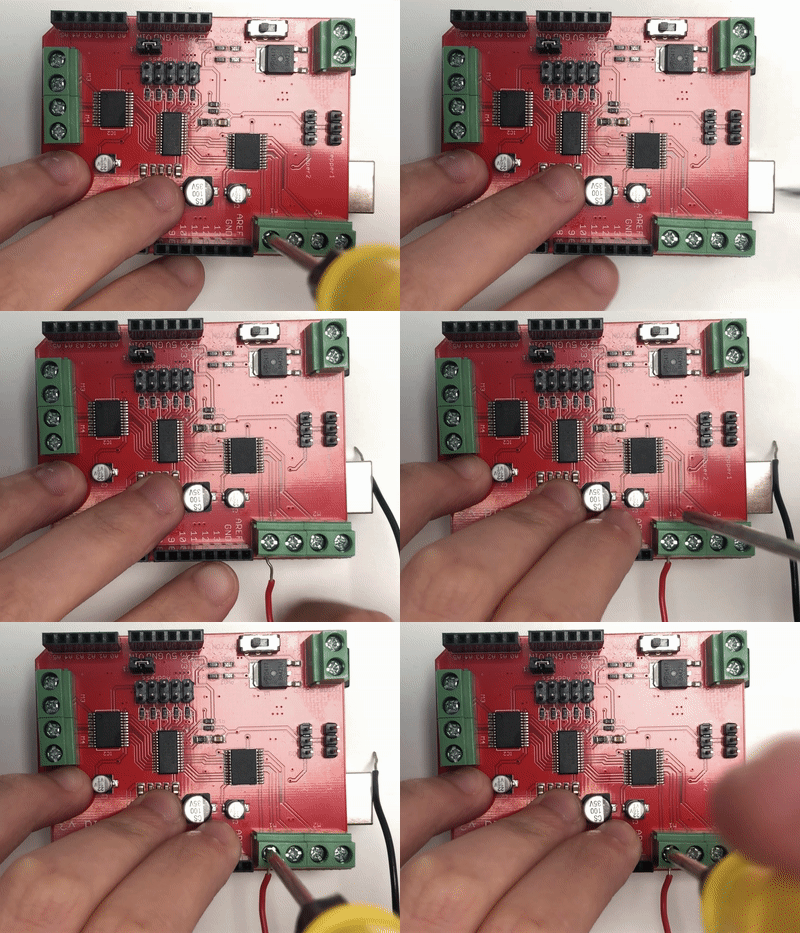
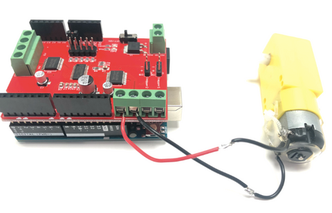
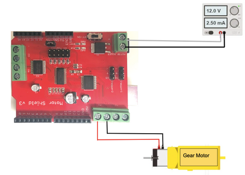
To control a motor using the CAROBOT Motor Shield, first plug the motor's positive (red) wire into one of Channel A's terminal on the motor shield, and the motor's ground (black) wire into the other Channel A's terminal on the shield.
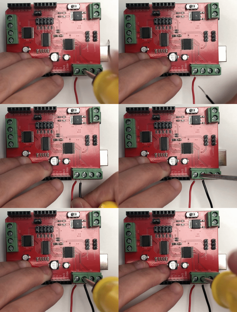
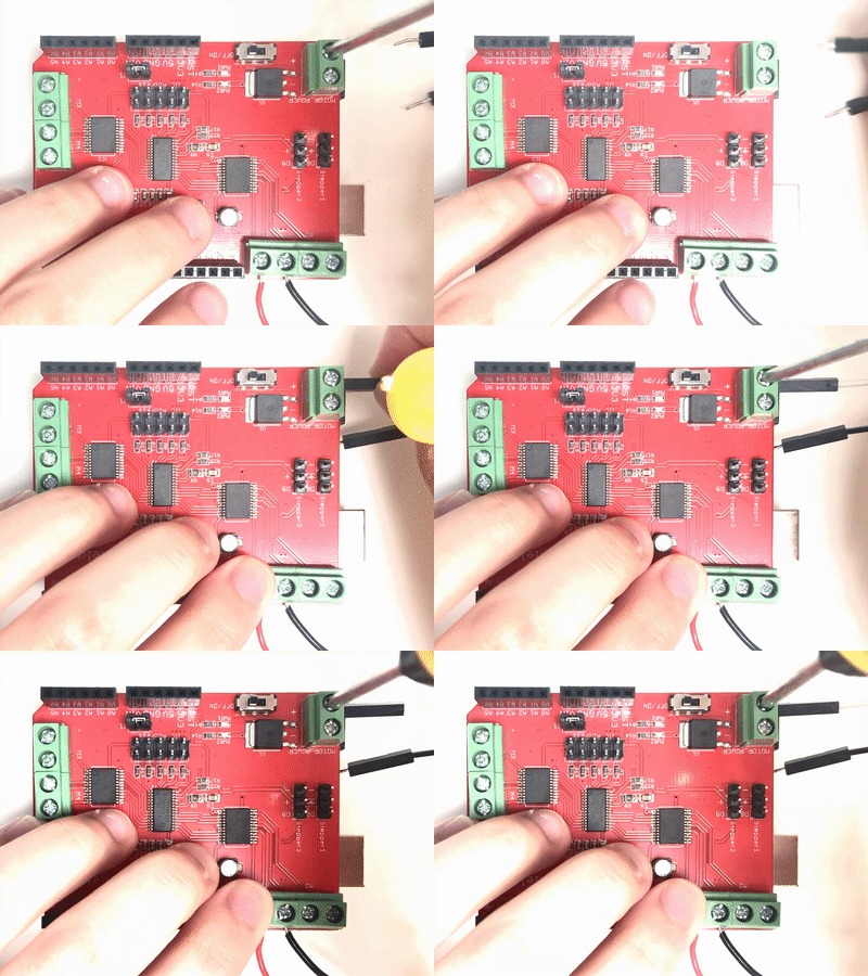
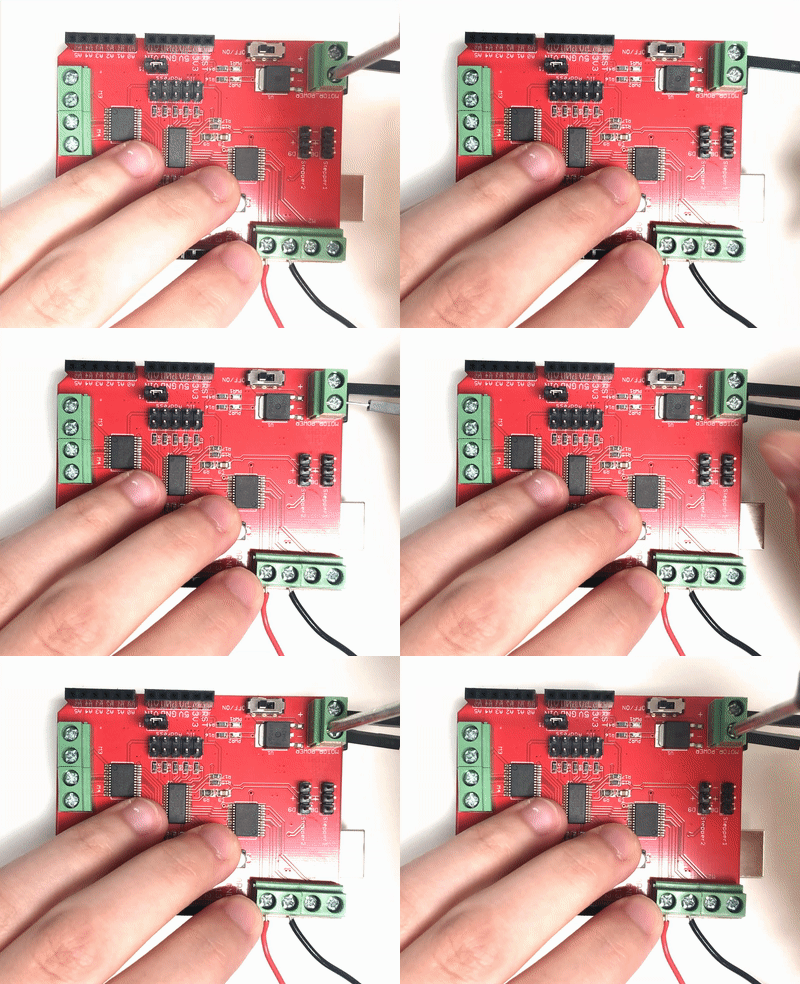
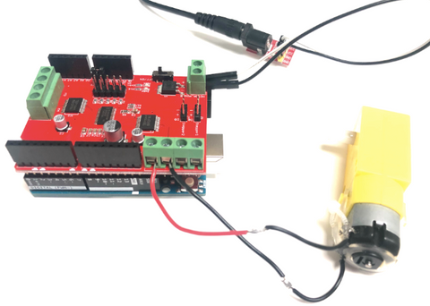
Next, connect your external power supply to the CAROBOT Motor Shield. Connect the positive (red) wire from the power supply to the "VIN" terminal, and the ground (black) wire to the "GND" terminal.
 |  |
|---|---|
 |  |
Programming
To begin controlling motors, you will need to install the motor shield library online.
Step 1: Go to Arduino > Sketch > Include Library > Manage Libraries

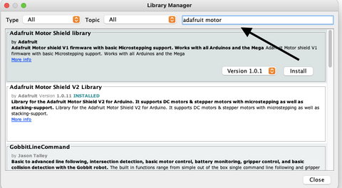
Step 2: Type in "Adafruit motor" to locate the library.
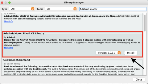
Step 3: Find "Adafruit Motor Shield V2 Library" and click Install.
Step 4: Go to Arduino > Sketch > Include Library and you will be able to see the library installed onto your Arduino.
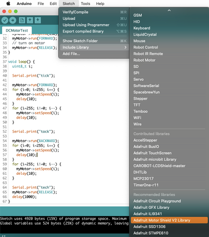
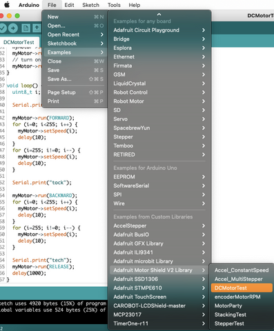
Step 5: Once you have installed the library, go to File > Examples > Adafruit_MotorShield > DCMotorTest
Code Explanation
Step 1: Include libraries
#include <Wire.h>
#include <Adafruit_MotorShield.h>
Step 2: Create a motor object to control the motor
Adafruit_MotorShield AFMS = Adafruit_MotorShield();
Step 3: Define the connection pin. We connected the motor in M1 channel, so we will use AFMS.getMotor(1).
Adafruit_DCMotor *myMotor = AFMS.getMotor(1);
Step 4: Set up serial communication between Arduino and the motor and print out message.
void setup() {
  Serial.begin(9600);
  Serial.println("Adafruit Motorshield v2 - DC Motor test!");
Step 5: Let the program begin and set the speed and turn on the motor.
  AFMS.begin();  // create with the default frequency 1.6KHz

  // Set the speed to start, from 0 (off) to 255 (max speed)
  myMotor->setSpeed(150);
  myMotor->run(FORWARD);
  // turn on motor
  myMotor->run(RELEASE);
}
Step 6: Let the motor go forward and set the speed to increase 1 every time until it reaches to the max speed.
void loop() {
  uint8_t i;

  Serial.print("tick");

  myMotor->run(FORWARD);
  for (i=0; i<255; i++) {
    myMotor->setSpeed(i);
    delay(10);
  }
Step 7: Once the motor reaches to the max speed, it will slow down and decrease its speed by 1 each time.
 for (i=255; i!=0; i--) {
    myMotor->setSpeed(i);
    delay(10);
  }
Step 8: Let the motor move backwards and set the speed to increase 1 every time until it reaches to the max speed.
myMotor->run(BACKWARD);
  for (i=0; i<255; i++) {
    myMotor->setSpeed(i);
    delay(10);
  }
Step 9: Once the motor reaches to the max speed, it will slow down and decrease its speed by 1 each time.
for (i=255; i!=0; i--) {
    myMotor->setSpeed(i);
    delay(10);
  }
Step 10: set the motor to go full speed and delay for 1 second.
myMotor->run(RELEASE);
  delay(1000);
}
Full Code:
#include <Wire.h>
#include <Adafruit_MotorShield.h>

Adafruit_MotorShield AFMS = Adafruit_MotorShield();

Adafruit_DCMotor *myMotor = AFMS.getMotor(1);

void setup() {
  Serial.begin(9600);
  Serial.println("Adafruit Motorshield v2 - DC Motor test!");

  AFMS.begin();  // create with the default frequency 1.6KHz

  // Set the speed to start, from 0 (off) to 255 (max speed)
  myMotor->setSpeed(150);
  myMotor->run(FORWARD);
  // turn on motor
  myMotor->run(RELEASE);
}

void loop() {
  uint8_t i;

  Serial.print("tick");

  myMotor->run(FORWARD);
  for (i=0; i<255; i++) {
    myMotor->setSpeed(i);
    delay(10);
  }
  for (i=255; i!=0; i--) {
    myMotor->setSpeed(i);
    delay(10);
  }

  Serial.print("tock");

  myMotor->run(BACKWARD);
  for (i=0; i<255; i++) {
    myMotor->setSpeed(i);
    delay(10);
  }
  for (i=255; i!=0; i--) {
    myMotor->setSpeed(i);
    delay(10);
  }

  Serial.print("tech");
  myMotor->run(RELEASE);
  delay(1000);
}
Output
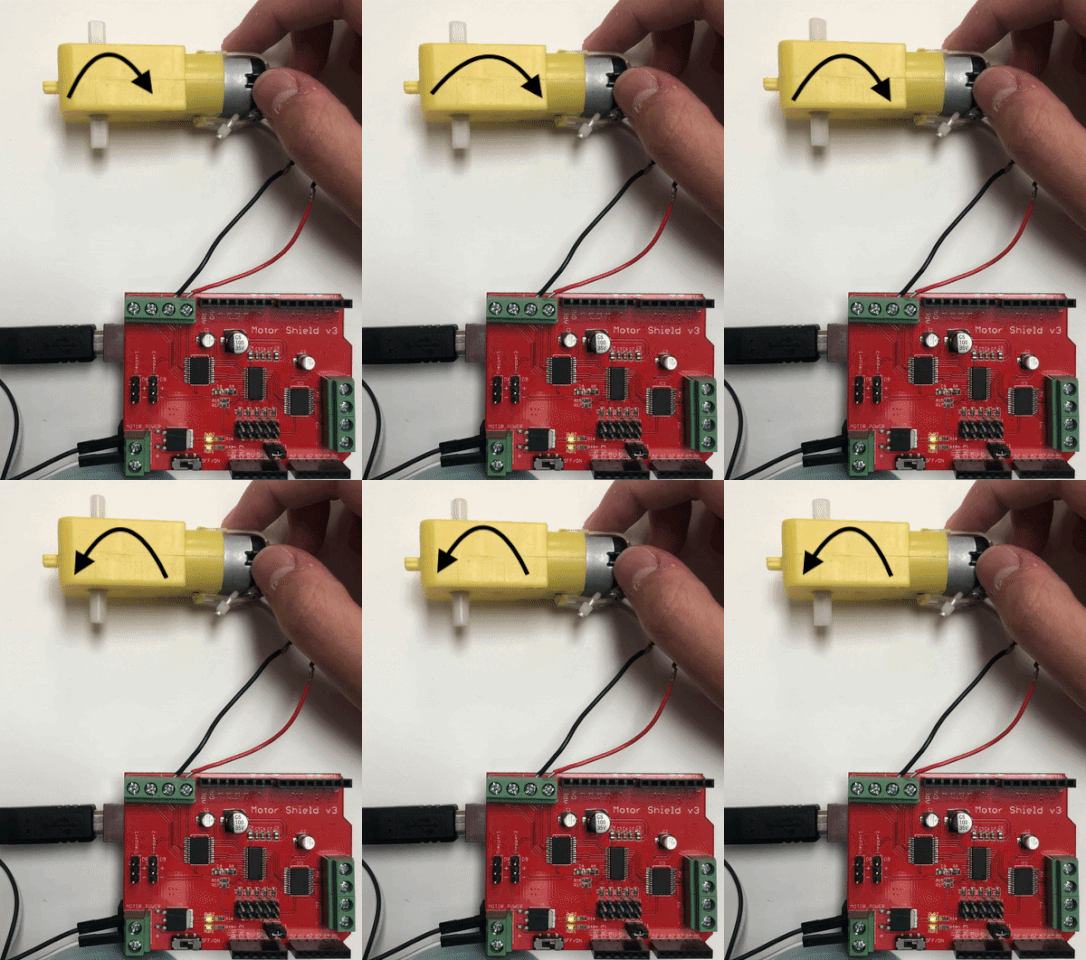
Now, you should see the DC motor turn on and move back and forth.
Connecting a servo motor onto the Shield
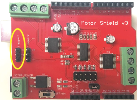
Hobby servos are the easiest way to get going with motor control. They consist of 3 pins: +5V, GND and signal inputs. The motor brings out the PWM output lines from Arduino pins 8 and 9 to two 3-pin headers so that it is easier to plug in and go.
To control a motor using the CAROBOT Motor Shield, first plug the servo motor's pins into the headers.
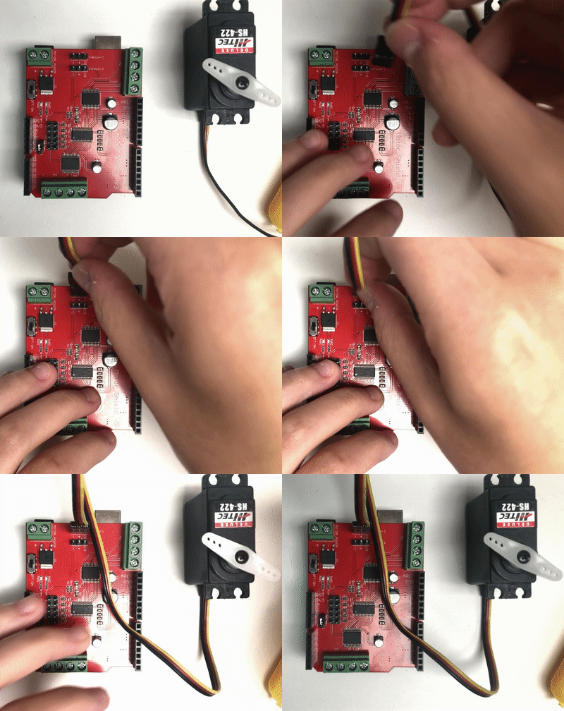
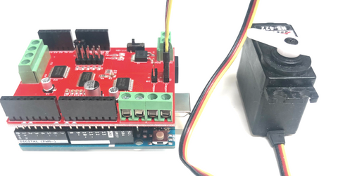
We do not need an external power supply for the servo motor as the motor receives power from the Arduino's on-board 5V regulator, powered directly from the USB or DC power jack on the Arduino.
Programming
There is a built-in Servo Library in Arduino that you can use for this project.
Step 1: Go to File > Examples > Servo > Sweep
Step 2: Change the connection pin to be pin 8 instead of 9.
void setup() {
  myservo.attach(8);  // attaches the servo on pin 9 to the servo object
}
Code Explanation
Step 1: Include Library
#include <Servo.h>
Step 2: Create a servo object to control the servo
Servo myservo; // create servo object to control a servo
Step 3: Create a variable to store the position of the servo
int pos = 0; // variable to store the servo position
Step 4: Define the connection pin
void setup() {
  myservo.attach(8);  // attaches the servo on pin 9 to the servo object
}
Step 5: The servo will go from 0 degree to 180 degree by adding 1 degree each time and delay for 15 milliseconds.

void loop() {
  for (pos = 0; pos <= 180; pos += 1) { // goes from 0 degrees to 180 degrees
    // in steps of 1 degree
    myservo.write(pos);              // tell servo to go to position in variable 'pos'
    delay(15);                       // waits 15ms for the servo to reach the position
  }
Step 6: The servo will go back to the original position from 180 degree to 0 degree by decreasing 1 degree each other and delay for 15milliseconds.
for (pos = 180; pos >= 0; pos -= 1) { // goes from 180 degrees to 0 degrees
    myservo.write(pos);              // tell servo to go to position in variable 'pos'
    delay(15);                       // waits 15ms for the servo to reach the position
  }
}
Full Code:
#include <Servo.h>

Servo myservo;  // create servo object to control a servo

int pos = 0;    // variable to store the servo position

void setup() {
  myservo.attach(8);  // attaches the servo on pin 9 to the servo object
}

void loop() {
  for (pos = 0; pos <= 180; pos += 1) { // goes from 0 degrees to 180 degrees
    // in steps of 1 degree
    myservo.write(pos);              // tell servo to go to position in variable 'pos'
    delay(15);                       // waits 15ms for the servo to reach the position
  }
  for (pos = 180; pos >= 0; pos -= 1) { // goes from 180 degrees to 0 degrees
    myservo.write(pos);              // tell servo to go to position in variable 'pos'
    delay(15);                       // waits 15ms for the servo to reach the position
  }
}
Output
Now, you should be able to see the servo motor arm going back and forth.
