How to use The Photodiode Module
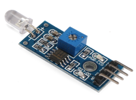
The Photodiode Module can be used for measuring brightness and ambient light intensity and is often used in robotics application. Compared to a photo-resistor, photodiode is better in directionality. Therefore, photodiode is better suited when searching for a light source whereas photoresistor is better for generic light intensity measurement.
Wiring
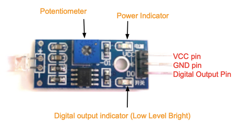
The photodiode module operates at 3.3V to 5V, and the digital output pin gives out a HIGH or LOW signal depending on the light intensity level. When ambient light intensity does not reach the threshold value, the "D0" port outputs a high lever; When the ambient light intensity exceeds a set threshold, the "D0" outputs a low lever.
There are a few types of photodiode modules in the market where they have different functions and advantages, such as adjusting the sensitivity. We will be using the Photodiode Module, the one we carry in our shop.
This module consists of 3 pins that allow it to connect to a microcontroller easily, like Arduino.
- GND: Ground pin to connect the sensor to the ground with the microcontroller
- VCC: Power pin for 3.3V to 5V operation voltage with the microcontroller
- D0: Digital output pin based on a predefined threshold through the potentiometer and the operation voltage of the microcontroller.
Parts
- Photodiode Module
- Arduino Uno R3
- Jumper wires
- Arduino IDE
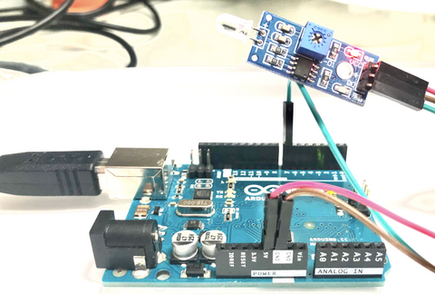
Wiring Guide
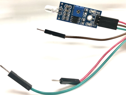
Connect the pins with female to male jumper wires
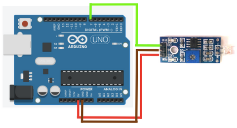
- Photodiode Module GND pin -- Arduino GND pin
- Photodiode Module VCC pin -- Arduino 5V pin
- Photodiode D0 pin -- Arduino D7 pin
Programming
In the following code, we want the internal Led to be on when it detects something in front of it (in other words, when the brightness level is low). If you want to skip the steps, you can jump to the Full Code.
Step 1: Define the connection pins
#define sensor 7
#define internal_led 13
Step 2: Create a variable to store the digital state of the module
int value = 0;
Step 3: Set up serial communication between Arduino and the module, and set the sensor as input and the internal led as output. This way, the sensor will send the signal to Arduino, and Arduino will act upon it to the internal led depending on the state of the sensor.
void setup(){
  Serial.begin(9600);
  pinMode(sensor, INPUT);
  pinMode(internal_led, OUTPUT);
}
Step 4: Get digital output from sensor
void loop(){
  value = digitalRead(sensor);
Step 5: Determine the brightness level or if there is something in front of the photodiode sensor. If so, the internal led will be turned on. Otherwise, it will be turned off.
 if (value == HIGH){ // in front of it
    digitalWrite(internal_led, HIGH);
    Serial.println("HIGH");
  }
  else{
    digitalWrite(internal_led, LOW);
    Serial.println("LOW");
  }
}
Full Code
#define sensor 7
#define internal_led 13

int value = 0;
void setup(){
  Serial.begin(9600);
  pinMode(sensor, INPUT);
  pinMode(internal_led, OUTPUT);
}

void loop(){
  value = digitalRead(sensor);
  if (value == HIGH){ // in front of it
    digitalWrite(internal_led, HIGH);
    Serial.println("HIGH");
  }
  else{
    digitalWrite(internal_led, LOW);
    Serial.println("LOW");
  }
}
Output
The internal led will turn on when it detects something in front of it, in this case, I covered the photodiode with my finger to demonstrate the detection. Also, the serial monitor will display a message according to the detection.
When it does not detect anything in front of it.
![]()
When it detects something in front of it.
![]()