How to use The LCD Shield Kit
LCD is widely used in applications to show characters and messages other than using the serial monitor. Our LCD shield kit makes it easy for you you to connect a LCD with an Arduino without using up any of the digital I/O pin except for the 2 I2C pins. As a result, you can connect more electronics into one shield, making it much easier to work with on the Arduino boards.
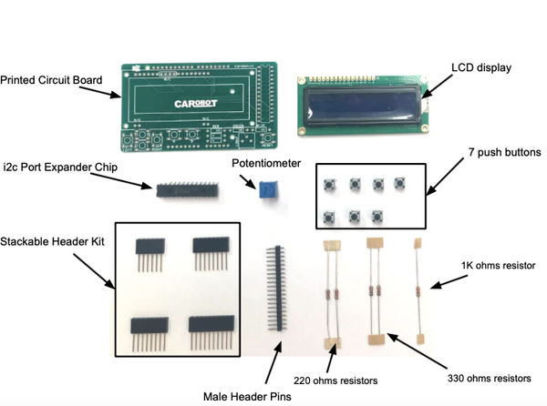
Part List
Equipment List
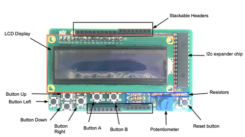
The LCD Shield Kit comes with the following parts.
Assembly
If you have already assembled the board, you can jump to the Wiring Guide.
Soldering Technique:
**With your soldering iron heated up and ready, solder in both leads of the resistors. To do this, heat the round ring pad and the wire lead at the same time for 2 to 3 seconds, then dip the end of the solder into the heated joint to melt it in. Then remove the solder and the soldering iron. **
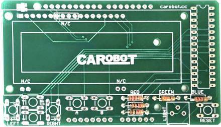
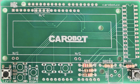
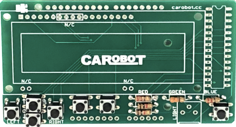
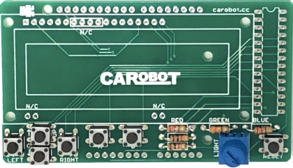
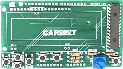
Step 1: Place the resistors onto the Circuit board. Bend the resistor into a 'staple' and slide it into the slot marked the corresponding ohms. Resistors do not have a direction to put it in either way, and it will work fine. After soldering the resistors, cut out the extra wire lead with a wire cutter.
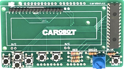
This is what it should look like when you soldered your resistors onto the circuit board.
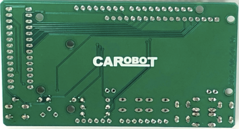
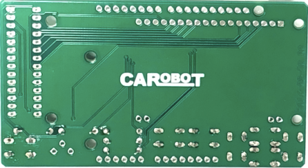
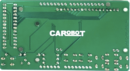
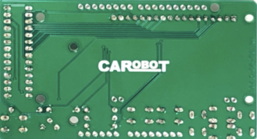
Front & Back:
Step 2: Place the button onto the circuit board and solder it from the back.
Second Button:
Front & Back:
Repeat the steps for the other buttons. After you soldered all of them, it will look like this.
Step 3: Place the potentiometer and solder it from the back.
Front & Back:
Step 4: Place the Chip and solder it from the back.
Step 5: Place the Male header pins and solder it from the back.
Front & Back:
Step 6: Place the LCD in the middle of the circuit board and solder it from the back.
Result:

Step 7: Place the Pins on the sides and solder it from the back.
Solder both sides
Front & Back:
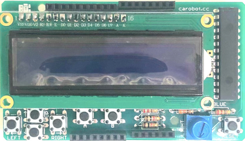
Final Build
Wiring Guide
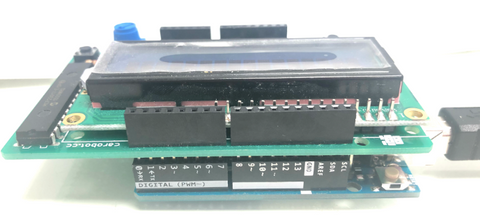
Simply stack the LCD Shield Kit onto Arduino Uno Board, then connect the board to your computer via a USB cable.
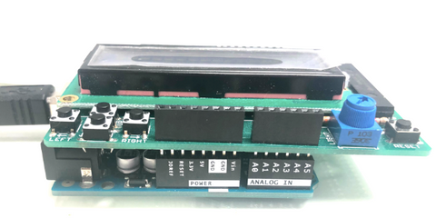
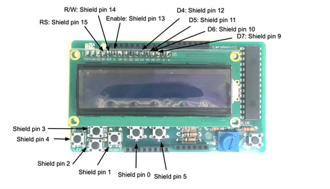
Wiring PinOut There are no connections to the Arduino since all the pins are connecting to the I2C chip. So, for example, telling the MCP23017 chip to set pin 1 high will set the GPA1 of the chip to high, which is connected to button A of the shield.
Noted that the pins are not referring to Arduino pins, it is referring to the Shield's pin.
If you want to take a look at the MCP23017 data sheet and have a better understanding of it.
| GPIO | Library Pin | Function |
|---|---|---|
| GPA0 | 0 | Button A |
| GPA1 | 1 | Button Right |
| GPA2 | 2 | Button Down |
| GPA3 | 3 | Button Up |
| GPA4 | 4 | Button Left |
| GPA5 | 5 | Button B |
| GPA6 | 6 | B/L Pri Red |
| GPA7 | 7 | B/L Green |
| GPB0 | 8 | B/L Blue |
| GPB1 | 9 | LCD DB7 |
| GPB2 | 10 | LCD DB6 |
| GPB3 | 11 | LCD DB5 |
| GPB4 | 12 | LCD DB4 |
| GPB5 | 13 | LCD Enable |
| GPB6 | 14 | LCD R/W |
| GPB7 | 15 | LCD RS |
Programming
The following code demonstrates how the I2C chip works and is connected to the components on the shield. In addition, it will show a basic hello world display and button input for the RGB 16x2 LCD Shield. If you want to skip all the steps, you can jump to the Full Code.
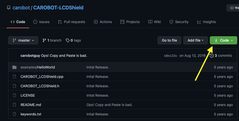
Step 1: Download the library from GitHub.
Click on "Code"
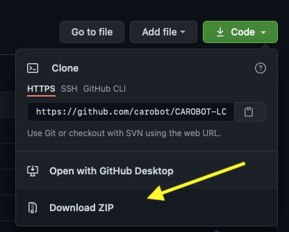
A window will show, and click on "Download ZIP". Your computer should start downloading the ZIP file.
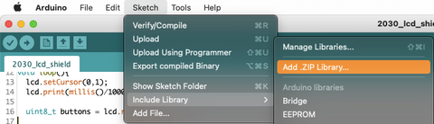
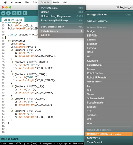
After downloading the ZIP file, open Arduino and go to Sketch > Include Library > Add .ZIP Library.
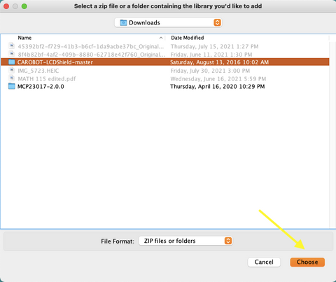
A pop-up window will appear. Click on the "CAROBOT-LCDShield-master" file and click on Choose.
As the window has closed, go to Sketch > Include Library > Contributed libraries. There you will see the library has been added to your Arduino.
Step 2: Include libraries
#include <Wire.h>
#include <CAROBOT_LCDShield.h>
Step 3: Define lcd
CAROBOT_LCDShield lcd;
Step 4: Set up the lcd, print a message to the LCD and set the backlight on.
void setup(){
  lcd.begin();
  lcd.print("Hello World");
  lcd.setBacklight(LCD_BL_ON);
}
Step 5: Set the cursor to column 0 and line 1 and print the number of seconds. Noted that line 1 is the second line as the counting begins with 0.
void loop(){
  lcd.setCursor(0,1);
  lcd.print(millis()/1000);
Step 6: Read the button inputs.
uint8_t buttons = lcd.readButtons();
Step 7: If the buttons are pressed, print out a message accordingly and change the backlight colour.
if (buttons){
    lcd.clear();
    lcd.setCursor(0,0);
    if (buttons & BUTTON_A){
      lcd.print("A ");
      lcd.setBacklight(LCD_BL_PURPLE);
    }
    if (buttons & BUTTON_RIGHT){
      lcd.print("RIGHT ");
      lcd.setBacklight(LCD_BL_BLUE);
    }
    if (buttons & BUTTON_DOWN){
      lcd.print("DOWN ");
      lcd.setBacklight(LCD_BL_YELLOW);
    }
    if (buttons & BUTTON_UP){
      lcd.print("UP ");
      lcd.setBacklight(LCD_BL_GREEN);
    }
    if (buttons & BUTTON_LEFT){
      lcd.print("LEFT ");
      lcd.setBacklight(LCD_BL_RED);
    }
    if (buttons & BUTTON_B){
      lcd.print("B ");
      lcd.setBacklight(LCD_BL_TEAL);
    }
  }

}
Full Code
#include <Wire.h>
#include <CAROBOT_LCDShield.h>

CAROBOT_LCDShield lcd;

void setup(){
  lcd.begin();
  lcd.print("Hello World");
  lcd.setBacklight(LCD_BL_ON);
}

void loop(){
  lcd.setCursor(0,1);
  lcd.print(millis()/1000);

  uint8_t buttons = lcd.readButtons();

  if (buttons){
    lcd.clear();
    lcd.setCursor(0,0);
    if (buttons & BUTTON_A){
      lcd.print("A ");
      lcd.setBacklight(LCD_BL_PURPLE);
    }
    if (buttons & BUTTON_RIGHT){
      lcd.print("RIGHT ");
      lcd.setBacklight(LCD_BL_BLUE);
    }
    if (buttons & BUTTON_DOWN){
      lcd.print("DOWN ");
      lcd.setBacklight(LCD_BL_YELLOW);
    }
    if (buttons & BUTTON_UP){
      lcd.print("UP ");
      lcd.setBacklight(LCD_BL_GREEN);
    }
    if (buttons & BUTTON_LEFT){
      lcd.print("LEFT ");
      lcd.setBacklight(LCD_BL_RED);
    }
    if (buttons & BUTTON_B){
      lcd.print("B ");
      lcd.setBacklight(LCD_BL_TEAL);
    }
  }

}
Output
After uploading the code, the first row will be the message we code to print previously, and the second row will be the number of seconds.
When "left" button is pressed
When "right" button is pressed
When "up" button is pressed
When "down" button is pressed
When "A" button is pressed
When "B" button is pressed
When twisting the potentiometer for the brightness of the LCD display
When "restart" button is pressed