How to use The HC-SR501 Sensor
HC-SR501 is based on infrared technology, an automatic control module with high sensitivity and ultra-low-voltage operating mode, making it highly reliable to use. It is widely used in various auto-sensing electrical equipment, like battery-powered automatic controlled products.
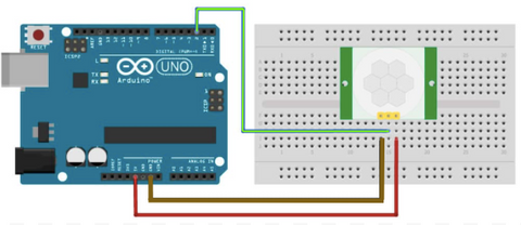
Wiring
The HC-SR501 sensor operates at 5V to 20V, and the digital output pin gives out a HIGH or LOW signal depending on if the sensor detects any motions. Thus, the sensor can be used without connecting to a microcontroller and just by a power supply and a load. For instance, it can be connected to the power supply and a lightbulb. Then, when it detects motion within its range (less than 120 degrees, within 7m), the digital output pin will be triggered and send a HIGH signal that gives power to the lightbulb to turn on.
There are a few types of similar motion sensors in the market where the main difference is they have a smaller detection range and do not have a potentiometer to adjust the sensitivity and time delay compared to the one we will be using, the HC-SR501 sensor, the one we carry in our shop.
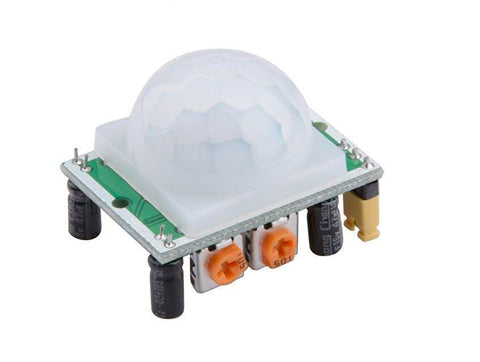
Under the white plastic shield, you will see the actual infrared sensor. The white plastic shield is used to reflect the motion from all around, making the sensor much more sensitive.
**The infrared sensor under the white plastic shield. **
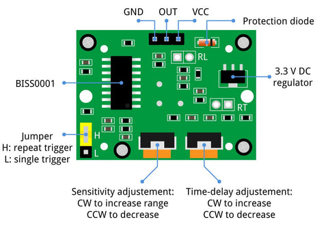
This module consists of 3 pins that allow it to connect to power supply, load or even a microcontroller easily, like an Arduino.
- GND: Ground pin to connect the sensor to the ground with the microcontroller or power supply
- VCC: Power pin for 5V to 20V operation voltage with the microcontroller or power supply
- OUT: Digital output pin based on a predefined threshold through the potentiometer and the operation voltage of the microcontroller or power supply.
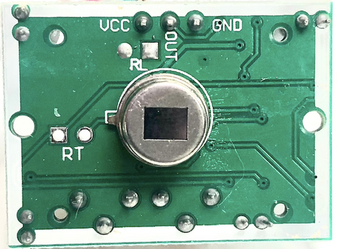
Back side of the module
Parts
Wiring Guide
Connect the pins with female to male jumper wires
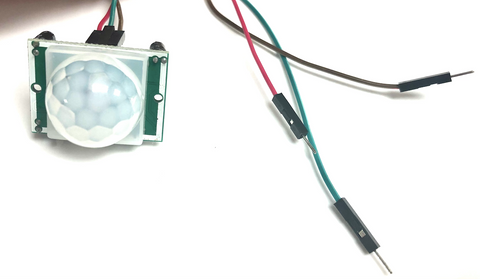
HC-SR501 sensor GND pin -- Arduino GND pin HC-SR501 sensor VCC pin -- Arduino 5V pin HC-SR501 sensor OUT pin -- Arduino D2 pin
Programming
In the following code, we will read out the sensor. Next, the code will read the sensor's state (HIGH or LOW) and print a message to the Serial Monitor. The code can also be used to control simple relays to turn a bigger light on or off.
If you want to skip the steps, you can jump to the Full Code.
Step 1: Define the connection pin.
#define sensor 2
Step 2: Create a variable to store the sensor's state.
int state = 0;
Step 3: Set up serial communication between Arduino and the sensor and set the sensor as input. This way, the sensor can send signal to Arduino and Arduino will send out messages accordingly.
void setup() {
  Serial.begin(9600);// setup Serial Monitor to display information
  pinMode(sensor, INPUT);// Input from sensor
}
Step 4: Read the state of the sensor.
void loop() {
  state =digitalRead(sensor);
Step 5: If the sensor is triggered, print out "Motion detected". Otherwise, print "==nothing moves".
  if(state){
    Serial.println("Motion detected");
  }
  else{
     Serial.println("===nothing moves");
  }
Step 6: Stop for half a second.
  delay(500);

}
Full Code
#define sensor 2

int state = 0;

void setup() {
  Serial.begin(9600);// setup Serial Monitor to display information
  pinMode(sensor, INPUT);// Input from sensor
}

void loop() {
  state =digitalRead(sensor);
  if(state){
    Serial.println("Motion detected");
  }
  else{
     Serial.println("===nothing moves");
  }
  delay(500);

}
Output
It will print out a message according to its state whether if it detects anything within the range.
