Using the HC-SR501 PIR Motion Sensor with ESP-Wroom 32
Introduction
The goal of this tutorial is to demonstrate how to use HC-SR501 and ESP WROOM 32 to create a simple motion detector. You will learn how to wire the components, upload the code, and test the functionality. You will also learn some basic concepts of motion sensing, digital input/output, and serial communication.

Materials
To follow this tutorial, you will need the following materials:
Wiring and Setup
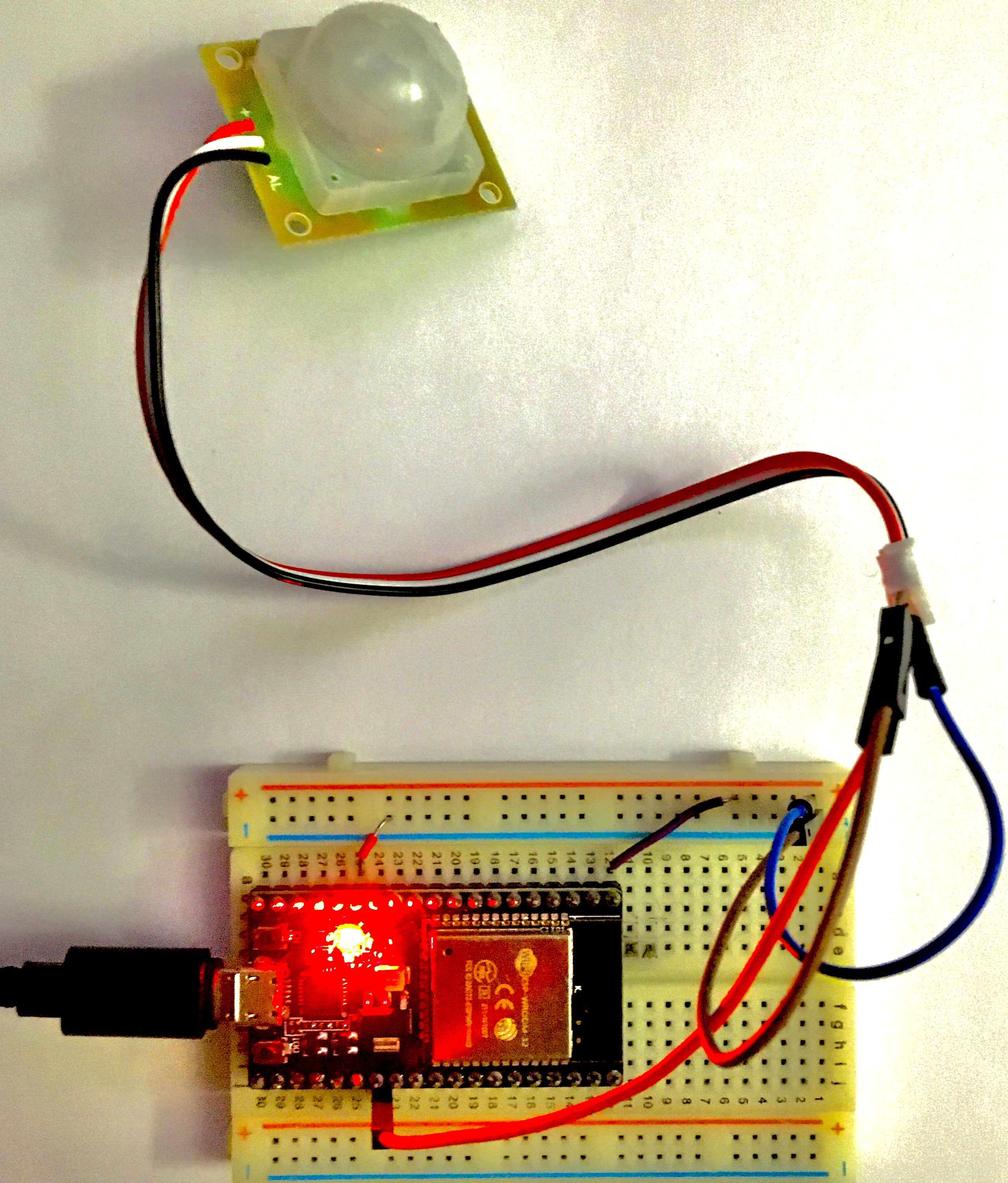
The wiring and setup of the AM2320 sensor and the ESP32 board depend on the communication mode you choose: single-wire or I2C. In this tutorial, we will use the I2C mode, which requires two resistors as pull-up for the SDA and SCL lines²³. The wiring diagram is shown below:

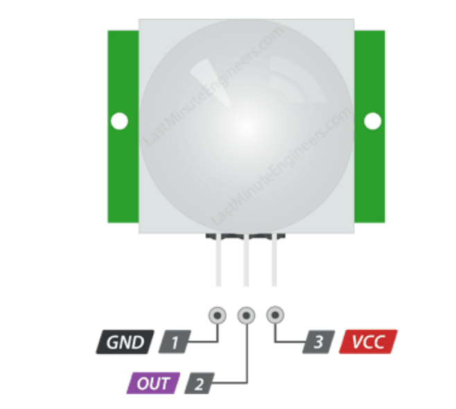
Below are the pinouts for each module:
The AM2320 temperature sensor is connected to an ESP-WROOM-32 microcontroller using the following pin configuration:
| AM2320 Temperature Sensor | ESP-WROOM-32 Pin |
|---|---|
| VCC | 3.3V |
| GND | GND |
| OUT | GPIO4 |
- Connect the VCC pin of the HC-SR501 to the 3.3V pin of the ESP-WROOM-32.
- Connect the GND pin of the HC-SR501 to the GND pin of the ESP-WROOM-32.
- Connect the OUT pin of the HC-SR501 to a GPIO4 pin on the ESP-WROOM-32 .
Full Code
int motionSensorPin = 2; // GPIO pin connected to the motion sensor

void setup() {
  Serial.begin(9600); // Initialize serial communication
  pinMode(motionSensorPin, INPUT); // Set motion sensor pin as input
}

void loop() {
  int motionDetected = digitalRead(motionSensorPin); // Read motion sensor pin state

  if (motionDetected == HIGH) {
    Serial.println("Motion detected!");
  } else {
    Serial.println("No motion detected.");
  }

  delay(1000); // Delay for 1 second
}
Programming & Logic
Let's go through the logic of the code line by line:
-
We start by declaring a variable motionSensorPin to hold the GPIO pin number connected to the motion sensor (in this case, GPIO 2).
-
In the setup() function:
-
We initialize serial communication at a baud rate of 9600 to communicate with the computer.
-
We set the motionSensorPin as an input pin using the pinMode() function.
-
-
In the loop() function:
-
We read the state of the motionSensorPin using the digitalRead() function and store it in the motionDetected variable.
-
If the motion sensor pin state is HIGH, we print "Motion detected!" to the serial monitor using Serial.println().
-
If the motion sensor pin state is LOW, we print "No motion detected." to the serial monitor.
-
We introduce a delay of 1 second using the delay() function.
-
Troubleshooting
- If you encounter any issues, make sure the wiring connections are correct.
- Check that the motion sensor is receiving power (3.3V) and properly grounded.
- Ensure the motion sensor's OUT pin is connected to the correct GPIO pin on the ESP-WROOM-32.
- Verify that you have selected the correct board and port settings in the Arduino IDE.
Output
The possible output in the serial monitor can vary depending on the motion detected or not detected by the HC-SR501 sensor. Here are two examples of the possible output:
- Output when motion is detected:
Motion detected!
Motion detected!
Motion detected!
- Output when no motion is detected:
Motion detected!
Motion detected!
Motion detected!
In the first example, the sensor continuously detects motion, so the "Motion detected!" message is printed repeatedly. In the second example, no motion is detected, so the "No motion detected." message is printed continuously. The output will reflect the real-time status of the motion detected by the sensor.

Possible applications:
-
Security Systems: The motion sensor can be used in security systems to detect unauthorized movement or intruders. When motion is detected, the ESP-WROOM-32 can trigger an alarm, send a notification to a smartphone, or activate surveillance cameras.
-
Home Automation: The motion sensor can be integrated into home automation systems to automate lighting, HVAC (heating, ventilation, and air conditioning), and other appliances based on occupancy. For example, lights can turn on automatically when someone enters a room and turn off when the room is vacant.
-
Smart Lighting: The motion sensor can be used to control lighting in various environments, such as staircases, hallways, and outdoor spaces. Lights can be turned on only when motion is detected, providing convenience and enhancing safety.
-
Automatic Door Opening: The motion sensor can be employed to automatically open doors when someone approaches, providing hands-free access to buildings, shops, or residential spaces.
Conclusion
In this tutorial, we have successfully learned how to interface the HC-SR501 PIR motion sensor with the ESP-WROOM-32 development board. By understanding the wiring connections, uploading the provided code, and comprehending the programming logic, you can build motion detection systems or incorporate this knowledge into your projects. Remember to troubleshoot any issues and utilize the serial monitor to observe the output. Enjoy experimenting with the capabilities of the HC-SR501 and ESP-WROOM-32!