How to use The HC-020K Encoder Module
This HC-020K encoder is very useful to sense the motor’s position and velocity. It can be connected to any microcontroller via the 3-pin header.
In this article, we'll talk about how to wire and set up the module for operation with an Arduino Board.
Wiring
Most HC-020K modules operate with 5V and produce a digital output within the range of 0V to 5V. It will provide a 5V output when the beam is blocked, and a 0V output when the beam is unblocked. Arduino can read the pulse train to determine how far the motor has travelled at what velocity. For this article, we'll be using HC-020K Encoder Module, the one we carry in our shop.
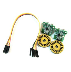
Parts
Wiring Guide
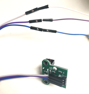
Connect the wires with male to male jumper wires.
Noted that the encoder comes with 3 female to female jumper wires to connect the pins.
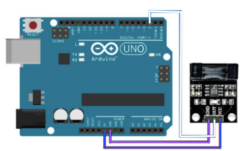
- HC-020K Encoder VCC (5V) -- Arduino 5V pin
- HC-020K Encoder GND -- Arduino GND pin
- HC-020K Encoder OUT -- Arduino D2 pin
- Gear Motor Terminal 1 -- Arduino 5V pin
- Gear Motor Terminal 2 -- Arduino GND pin
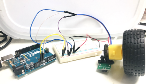
After completing the connection, connect Arduino Uno to a power supply with a USB cable.
Step 1: Connect the module's wires with a male to female jumper wires
Step 2: Connect the other side of the male to male wires to Arduino pins.
We used a breadboard to connect the pins because the encoder and the gear motor share the 5V from Arduino. We put male to male jumper wires from Arduino GND pin and 5V pin to the breadboard's negative and positive rail. Then, connect the encoder's GND pin and VCC pin onto the negative and positive rail respectively.
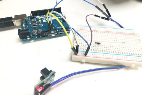
Step 3: Connect the gear motor to the Arduino by connecting the wires to negative and positive rail on the breadboard respectively (in this case, the black jumper wire is the negative, and the red wire is the positive).
Placing the slotted disc onto the gear motor.
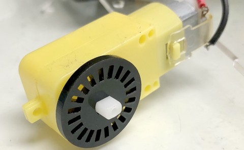
Step 1: Connect the slotted disc onto the plastic gear motor.
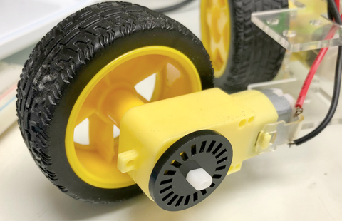
Step 2: Connect the wheel to the plastic gear motor.
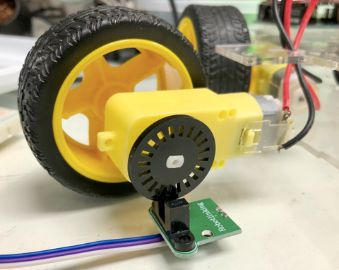
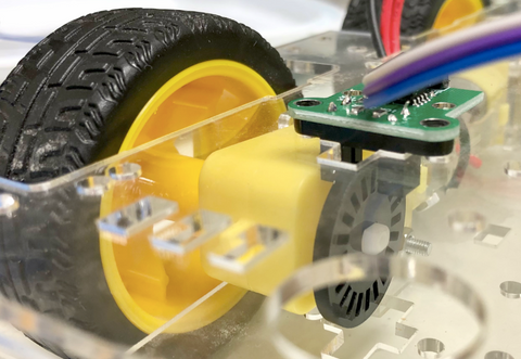
Step 3: Place the module onto the slotted disc, where the disc should be in between the two plastic on the module.
Full assemble: It should look like this where the slotted disc is placed in between the module gap.
Programming
The slotted disc is mounted to the plastic gear motor and placed within the space of the encoder circuit board. The optical beam sensor will detect the missing slots of the disc and generates a pulse train. From the code in Arduino, it will be able to detect the rpm for the plastic gear motor and display it on the Serial Monitor. If you want to skip the steps, you can jump to the Full Code.
Step 1: We will need to define the pin on Arduino Code by variable. From the code below, we defined the encoder to pin 2 as where we previously connected it to Arduino Uno.
#define encoder 2
Step 2: We need 4 variables to store the rpm, number of pulses occurred, time duration and the pulse per turn for the calculation of rpm. In the code, pulse_per_turn is set to 20, that is referred to the number of slots in the slotted disc.
unsigned int rpm;
volatile byte pulses;
unsigned long TIME;
unsigned int pulse_per_turn = 20;
//depends on the number of slots on the slotted disc
We will set the other variables to 0 in the setup method so they will be a signed value.
void setup(){
  //reset all to 0
  rpm = 0;
  pulses = 0;
  TIME = 0;
Step 3: We will set up the encoder as an input and a serial communication between Arduino Uno and the encoder to send and receive data to each other. We use the encoder pin (pin 2) where the IR detector is connected, to trigger on the variable, CHANGE which it will change the state from HIGH to LOW.
Serial.begin(9600);
  pinMode(encoder, INPUT);// setting up encoder pin as input
  //triggering count function everytime the encoder turns from HIGH to LOW
  attachInterrupt(digitalPinToInterrupt(encoder), count, FALLING);
}
Step 4: We will update the rpm calculation every 0.1 second by this line of code,
if (millis() - TIME >= 100){ // updating every 0.1 second
then we will stop the trigger and calculate for rpm.
//calcuate for rpm
    rpm = (60 *100 / pulse_per_turn)/ (millis() - TIME) * pulses;
After calculating for the rpm, we will reset the pulses, time and turn on the trigger, and print out the output result.
TIME = millis();
    pulses = 0;
    //print output
    Serial.print("RPM: ");
    Serial.println(rpm);
    //trigger count function everytime the encoder turns from HIGH to LOW
    attachInterrupt(digitalPinToInterrupt(encoder), count, FALLING);
Step 4 code:
void loop(){
  if (millis() - TIME >= 100){ // updating every 0.1 second
    detachInterrupt(digitalPinToInterrupt(encoder)); // turn off trigger
    //calcuate for rpm
    rpm = (60 *100 / pulses_per_turn)/ (millis() - TIME) * pulses;
    TIME = millis();
    pulses = 0;
    //print output
    Serial.print("RPM: ");
    Serial.println(rpm);
    //trigger count function everytime the encoder turns from HIGH to LOW
    attachInterrupt(digitalPinToInterrupt(encoder), count, FALLING);
  }
}
Full Code:
#define encoder 2

unsigned int rpm;
volatile byte pulses;
unsigned long TIME;
unsigned int pulse_per_turn = 20;
//depends on the number of slots on the slotted disc

void count(){
  // counting the number of pulses for calculation of rpm
  pulses++;
}
void setup(){
  //reset all to 0
  rpm = 0;
  pulses = 0;
  TIME = 0;

  Serial.begin(9600);
  pinMode(encoder, INPUT);// setting up encoder pin as input
  //triggering count function everytime the encoder turns from HIGH to LOW
  attachInterrupt(digitalPinToInterrupt(encoder), count, FALLING);
}

void loop(){
  if (millis() - TIME >= 100){ // updating every 0.1 second
    detachInterrupt(digitalPinToInterrupt(encoder)); // turn off trigger
    //calcuate for rpm
    rpm = (60 *100 / pulse_per_turn)/ (millis() - TIME) * pulses;
    TIME = millis();
    pulses = 0;
    //print output
    Serial.print("RPM: ");
    Serial.println(rpm);
    //trigger count function everytime the encoder turns from HIGH to LOW
    attachInterrupt(digitalPinToInterrupt(encoder), count, FALLING);
  }
}
Serial Monitor Output

