27. Stepper Motor
Stepper motors are widely used in various applications, from robotics to 3D printers, due to their precise control over rotation. In this tutorial, we will learn how to control a 28BYJ-48 stepper motor using an Arduino R4 and the L293D motor driver. The 28BYJ-48 stepper motor is a popular choice among hobbyists and makers for its low cost and ease of use. However, it requires a motor driver to interface with an Arduino, as the Arduino alone cannot provide enough current to drive the motor.
Materials
| Component | Image |
|---|---|
| Breadboard | 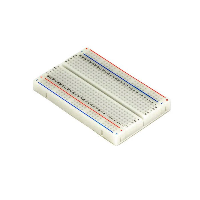 |
| Jumper wires | 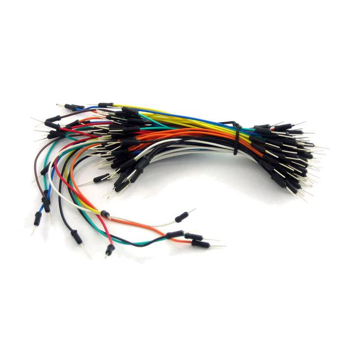 |
| Arduino Uno R4 Minima | 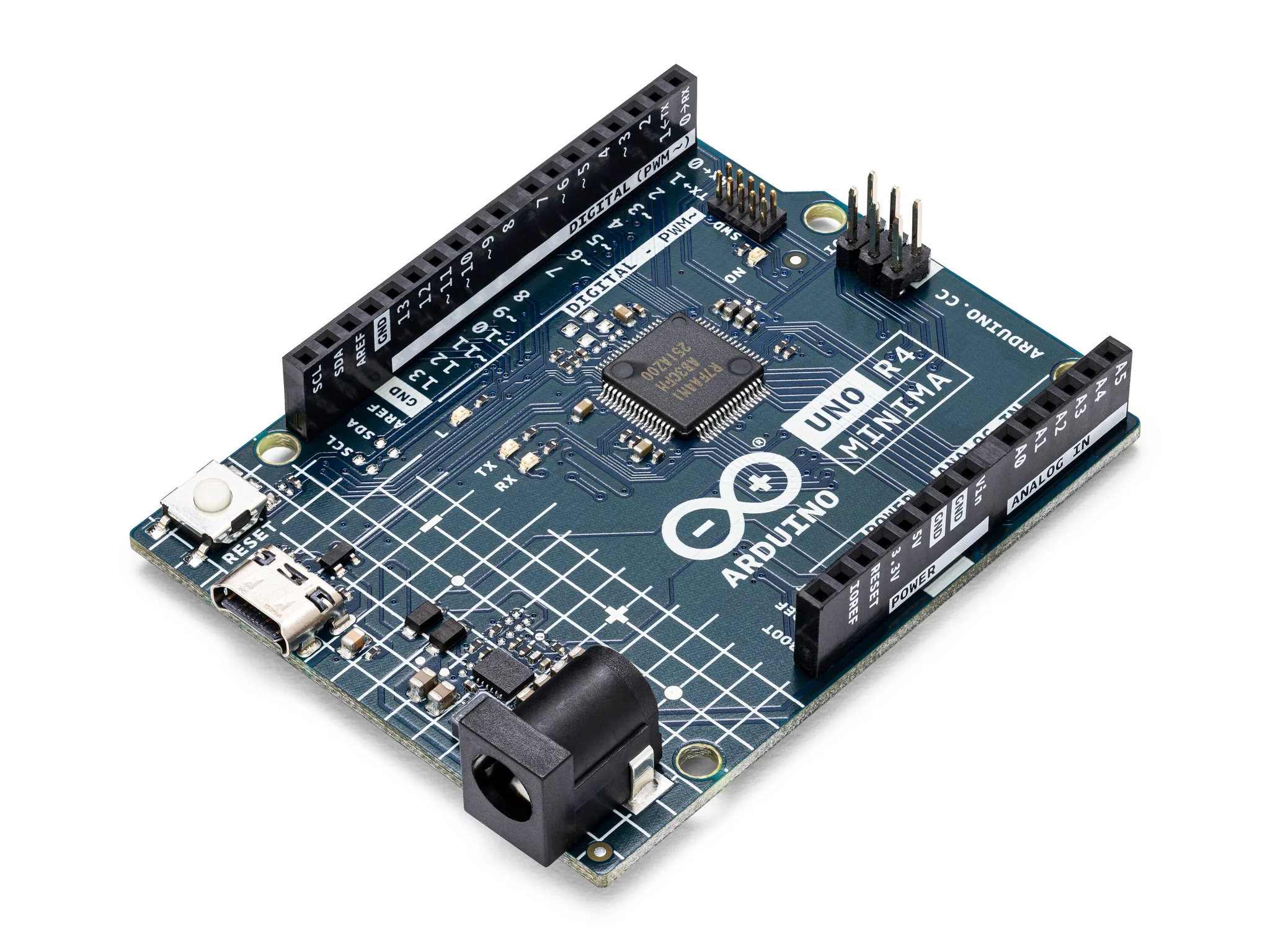 |
| ULN2003 Stepper Motor Driver Board and 28BYJ-48 Stepper Motor | 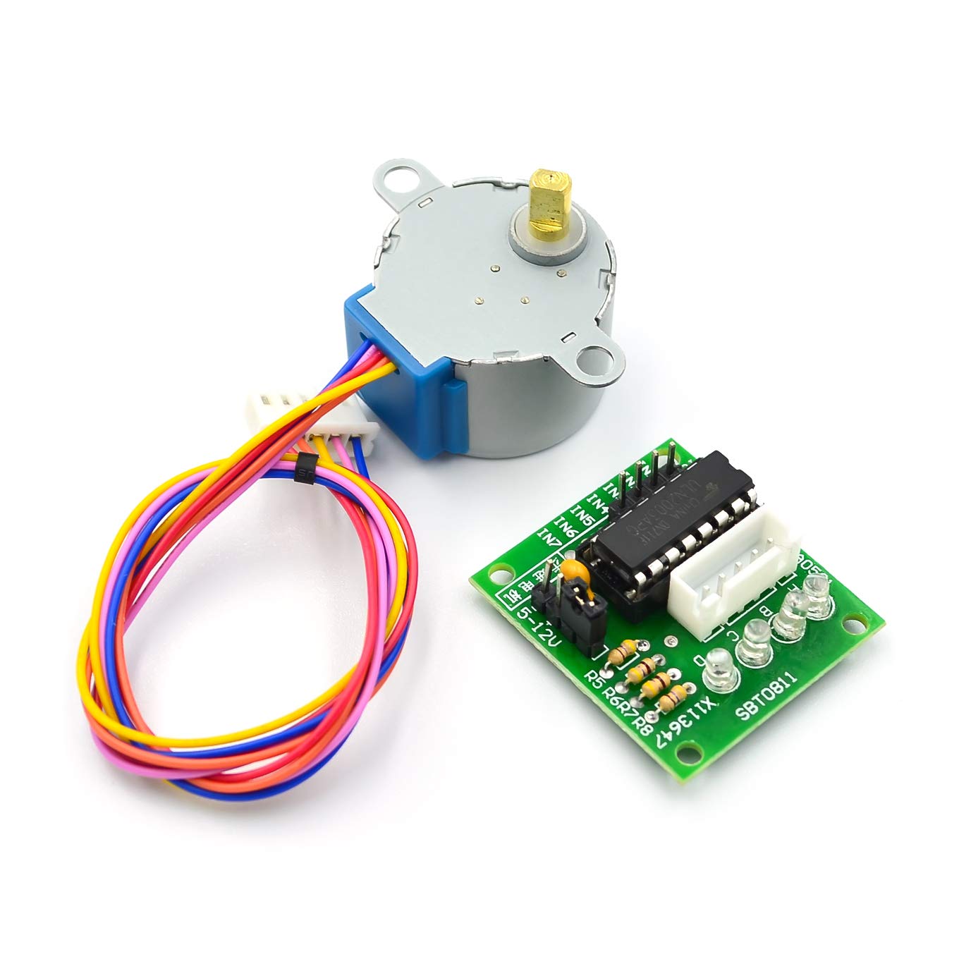 |
Instructions
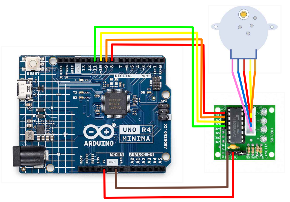
- Connect the four wires from the stepper motor to the OUT1, OUT2, OUT3, and OUT4 pins on the ULN2003 driver. Make the following connections using the breadboard and jumper wires.
ULN2003 Driver to the Arduino:
- + to 5V
- - to GND
- IN1 to pin 8
- IN2 to pin 9
- IN3 to pin 10
- IN4 to pin 11
-
Download the "Stepper.h" library on the Library Manager.
-
Paste the following code into your main Arduino sketch:
Code
#include <Stepper.h>

const int stepsPerRevolution = 2048;
const int rolePerMinute = 15;


Stepper myStepper(stepsPerRevolution, 8, 10, 9, 11);

void setup() {
  myStepper.setSpeed(rolePerMinute);

  Serial.begin(9600);
}

void loop() {

  Serial.println("clockwise");
  myStepper.step(stepsPerRevolution);
  delay(500);


  Serial.println("counterclockwise");
  myStepper.step(-stepsPerRevolution);
  delay(500);
}
-
Connect your Arduino to your laptop using a USB-C cable and upload the code to the arduino.
-
Test! Watch the stepper motor spin!
Controlling A Stepper With An IR Remote
In this tutorial, we'll learn how to control a stepper motor using an IR remote control with an Arduino. Stepper motors are commonly used in projects that require precise movement or rotation. By adding IR remote control functionality, we can wirelessly control the stepper motor's direction and speed.
Materials
In addition to everything from the previous section, you will also need:
| Component | Image |
|---|---|
| KY022 IR Receiver Module + Remote | 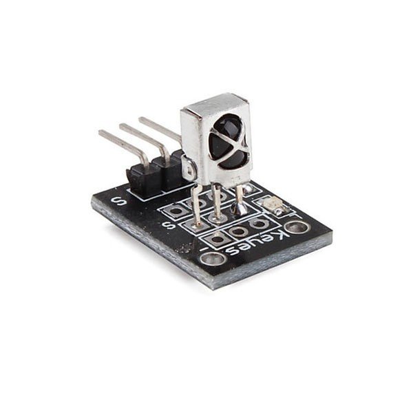 |
| IR Remote Control |  |
Instructions
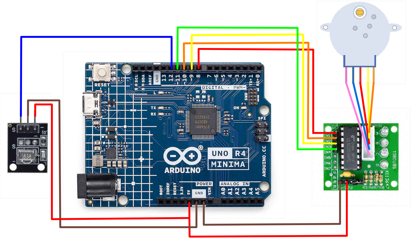
- Add the following connections to your current setup:
KY022 to Arduino R4
- S to pin 12
- + to 5V
- - to GND
- Switch the input pins for pins 8 and 9 on the Arduino R4.
- Paste the following code into your main Arduino sketch:
Code
#include "Stepper.h"
#include "IRremote.h"


#define STEPS 32
int Steps2Take;
int receiver = 12;


Stepper small_stepper(STEPS, 8, 9, 10, 11);
IRrecv irrecv(receiver);
decode_results results;

void setup() {
  Serial.begin(9600);
  irrecv.enableIRIn();
}

void loop() {
  if (irrecv.decode())
    Serial.println(irrecv.decodedIRData.decodedRawData, HEX);

  {
    switch (irrecv.decodedIRData.decodedRawData)

    {

      case 0xB946FF00:
        small_stepper.setSpeed(500);
        Steps2Take = 2048;
        small_stepper.step(Steps2Take);
        delay(2000);
        break;

      case 0xEA15FF00:
        small_stepper.setSpeed(500);
        Steps2Take = -2048;
        small_stepper.step(Steps2Take);
        delay(2000);
        break;
    }

    irrecv.resume();
    digitalWrite(8, LOW);
    digitalWrite(9, LOW);
    digitalWrite(10, LOW);
    digitalWrite(11, LOW);
  }


}
-
Connect your Arduino to your laptop using a USB-C cable and upload the code to the arduino.
-
Test! Use the IR Remote and see if the stepper motor spins.
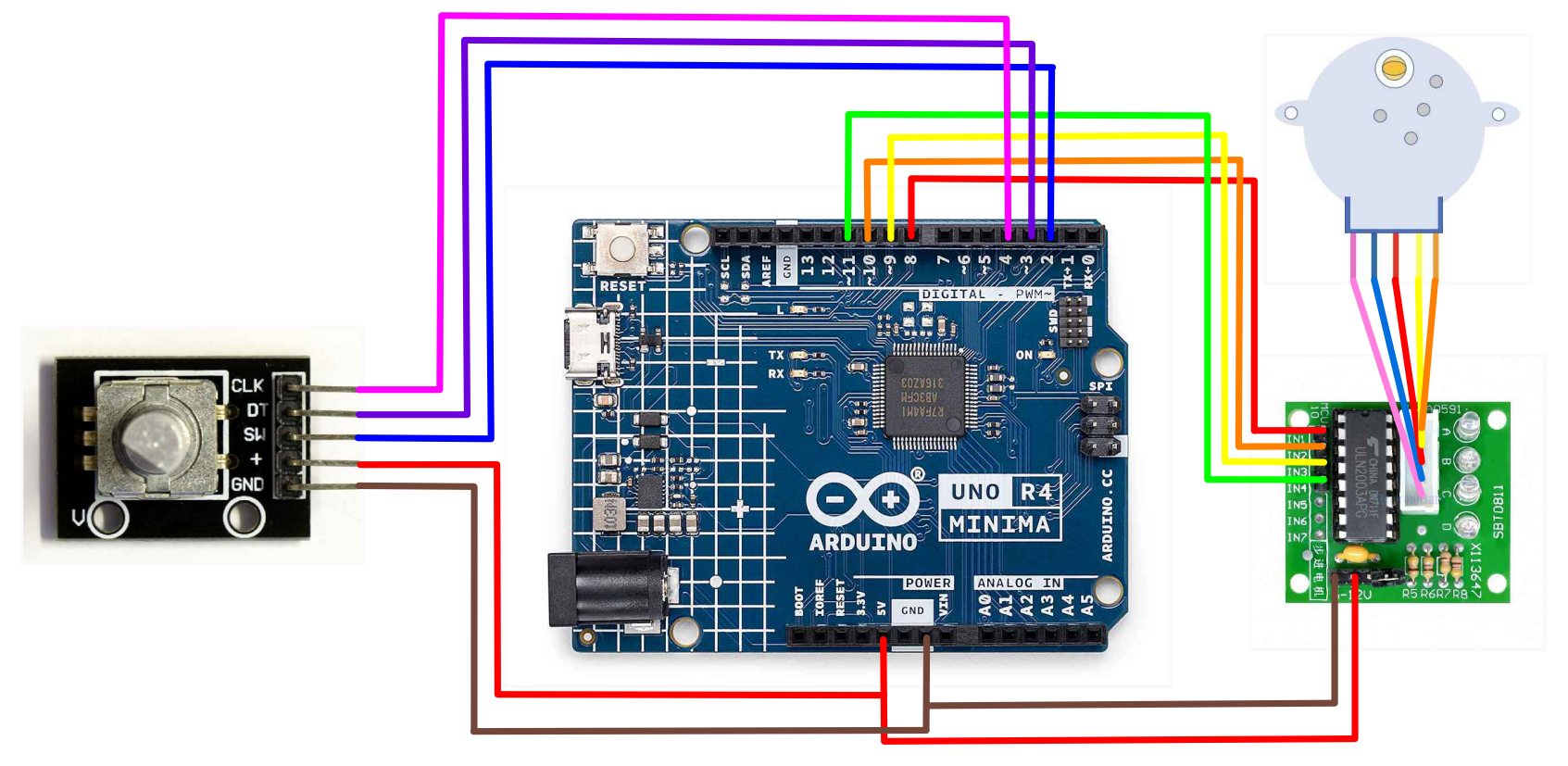
Controlling With A Rotary Encoder
Welcome to this tutorial on controlling a 28BYJ-48 stepper motor using a ULN2003 motor driver and an Arduino, guided by a rotary encoder. Stepper motors are precise control devices commonly used in robotics, CNC machines, and automation projects where precise movement is required. Combining a stepper motor with a rotary encoder allows for interactive control, making it possible to adjust the motor's position and speed with a simple twist of a knob.
Materials
In addition to everything from the firs section, you will also need:
| Component | Image |
|---|---|
| Rotary Encoder Module | 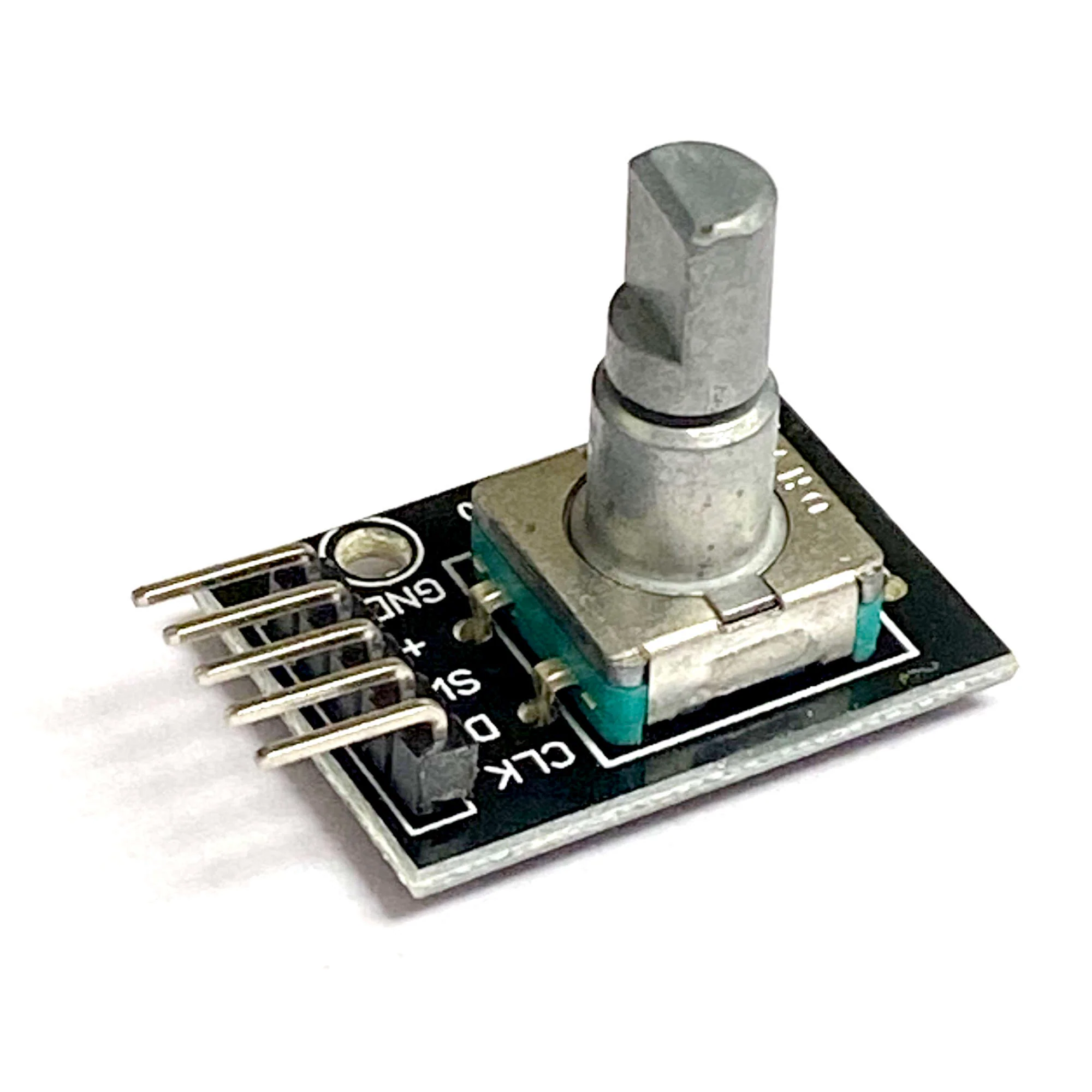 |
Instructions
- Add the following connections to the setup from the first section.
Rotary Encoder to the Arduino
- GND to GND
- + to 5V
- SW to pin 4
- DT to pin 3
- CLK to pin 2
- Paste the following code into your main Arduino sketch:
Code
#include <ezButton.h>  // the library to use for SW pin
#include <Stepper.h>   // the library for the stepper motor

#define CLK_PIN 2
#define DT_PIN 3
#define SW_PIN 4

#define DIRECTION_CW 0   // clockwise direction
#define DIRECTION_CCW 1  // counter-clockwise direction

const int stepsPerRevolution = 2048;  // 28BYJ-48 has 2048 steps per revolution
const int maxSpeed = 15;              // Maximum speed (RPM) for the stepper motor

int counter = 0;
int direction = DIRECTION_CW;
int CLK_state;
int prev_CLK_state;

Stepper myStepper(stepsPerRevolution, 8, 9, 10, 11);  // Initialize the stepper library on pins 8 through 11
ezButton button(SW_PIN);                              // create ezButton object that attach to pin 4

void setup() {
  Serial.begin(9600);

  // configure encoder pins as inputs
  pinMode(CLK_PIN, INPUT);
  pinMode(DT_PIN, INPUT);
  button.setDebounceTime(50);  // set debounce time to 50 milliseconds

  // read the initial state of the rotary encoder's CLK pin
  prev_CLK_state = digitalRead(CLK_PIN);

  // Set the motor speed
  myStepper.setSpeed(maxSpeed);
}

void loop() {
  button.loop();  // MUST call the loop() function first

  // read the current state of the rotary encoder's CLK pin
  CLK_state = digitalRead(CLK_PIN);

  // If the state of CLK is changed, then pulse occurred
  // React to only the rising edge (from LOW to HIGH) to avoid double count
  if (CLK_state != prev_CLK_state && CLK_state == HIGH) {
    // if the DT state is HIGH
    // the encoder is rotating in counter-clockwise direction => decrease the counter
    if (digitalRead(DT_PIN) == HIGH) {
      if (counter > -9) {
        counter--;
        direction = DIRECTION_CCW;
      }
    } else {
      // the encoder is rotating in clockwise direction => increase the counter
      if (counter < 9) {
        counter++;
        direction = DIRECTION_CW;
      }
    }

    Serial.print("DIRECTION: ");
    if (direction == DIRECTION_CW)
      Serial.print("Clockwise");
    else
      Serial.print("Counter-clockwise");

    Serial.print(" | COUNTER: ");
    Serial.println(counter);

    // Control the stepper motor based on the counter value
    if (direction == DIRECTION_CW) {
      myStepper.step(stepsPerRevolution / 100);  // Move a small step clockwise
    } else {
      myStepper.step(-stepsPerRevolution / 100);  // Move a small step counter-clockwise
    }
  }

  // save last CLK state
  prev_CLK_state = CLK_state;

  if (button.isPressed()) {
    Serial.println("The button is pressed");
    counter = 0;            // Reset counter when the button is pressed
  }
}
-
Connect your Arduino to your laptop using a USB-C cable and upload the code to the arduino.
-
Test! Twist the rotary encoder and press the button! Observe the stepper motors movements and the serial monitor to track the counter.
| Prev | Next |
|---|---|
| 26. DC Motor and Relay | N/A |