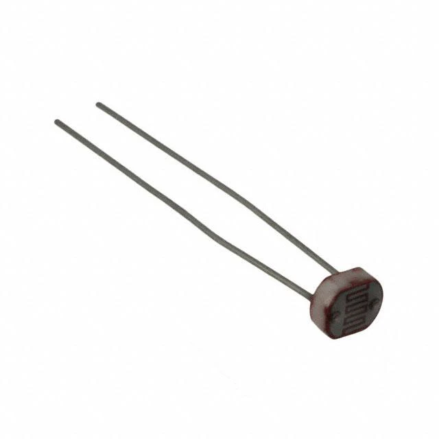
23. Photocell
Photocells, also known as photoresistors or light-dependent resistors (LDRs), are simple yet powerful components that can detect changes in light intensity. These components are commonly used in various applications such as automatic lighting systems, light-sensitive alarms, and other projects where light detection is essential.
Materials
Instructions
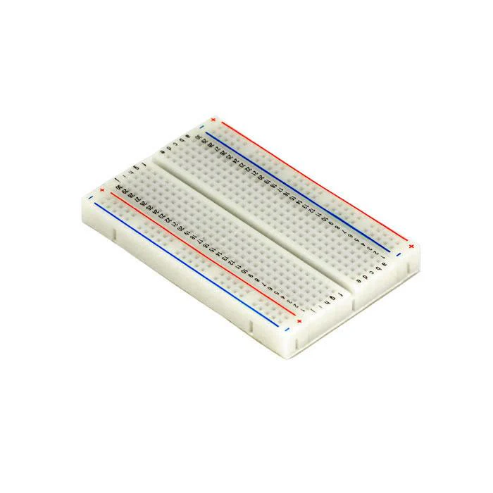
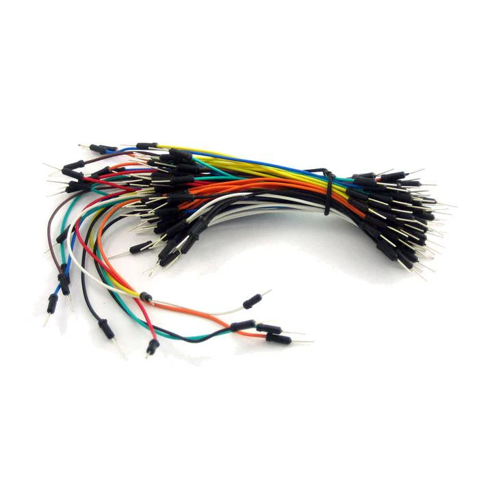
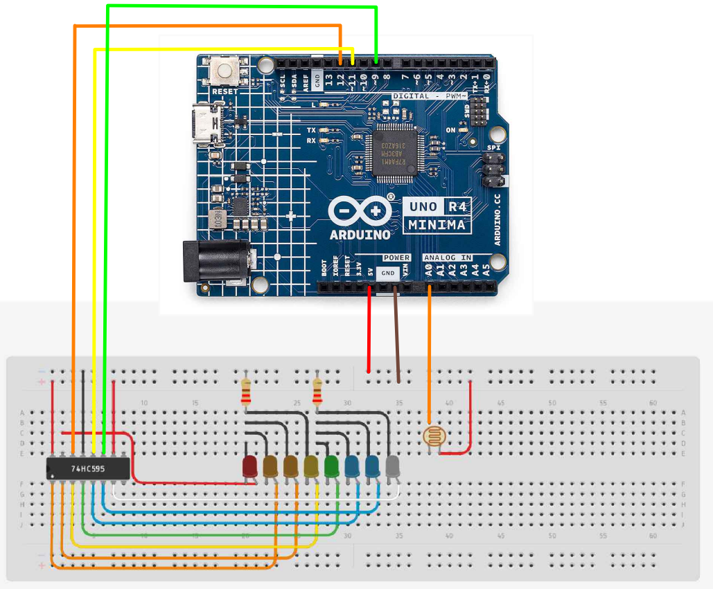
- Make the following connections using the breadboard and jumper wires.
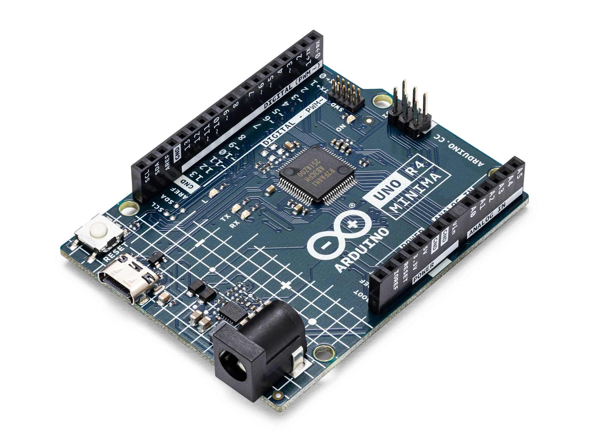
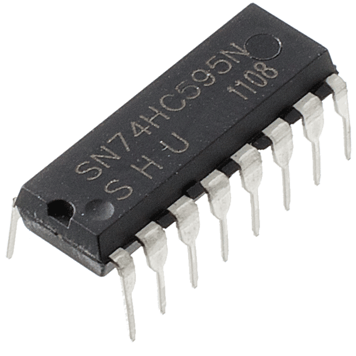
Arduino to Shift Register:
- latchPin (pin 11) to ST_CP (pin 12) of the 74HC595.
- clockPin (pin 9) to SH_CP (pin 11) of the 74HC595.
- dataPin (pin 12) to DS (pin 14) of the 74HC595.
Shift Register to LEDs:
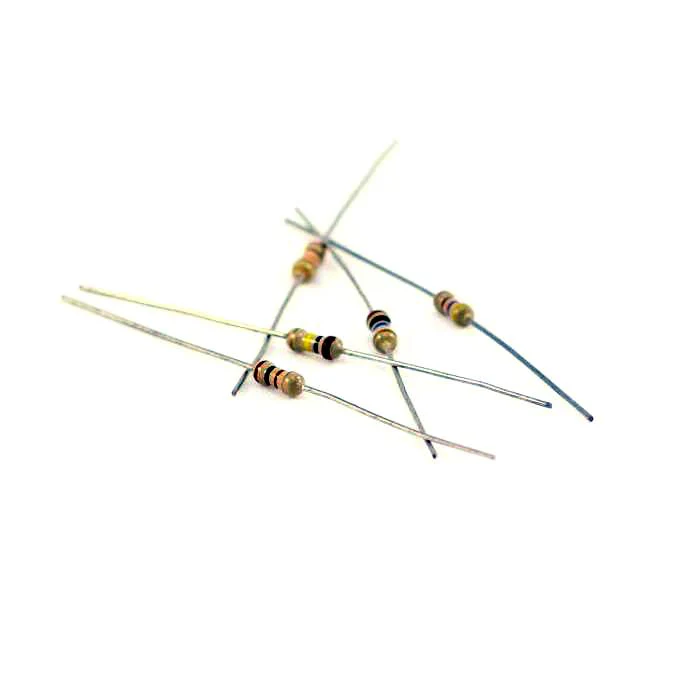
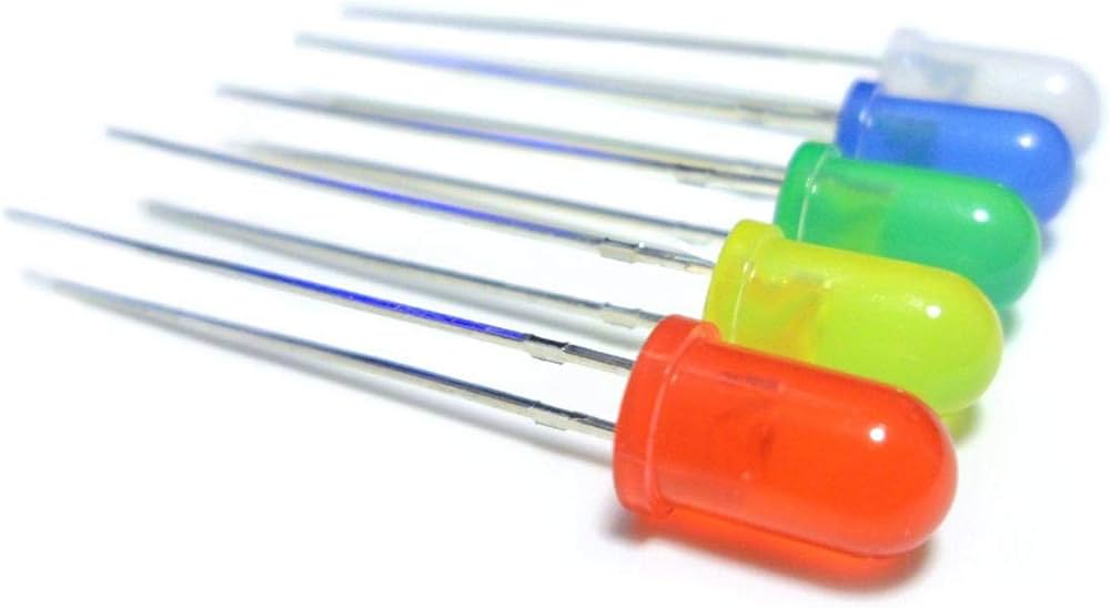
- Connect the output pins (Q0-Q7) of the 74HC595 to the anodes of the LEDs through current-limiting resistors (usually around 220 ohms).
Power Supply:
Connect VCC of the 74HC595 to a 5V power source. Connect GND of the 74HC595 to the Arduino's GND.
- Paste the following code into your main Arduino sketch:
Code
int lightPin = A0;
int latchPin = 11;
int clockPin = 9;
int dataPin = 12;

void setup() {
  Serial.begin(9600);
  pinMode(latchPin, OUTPUT);
  pinMode(clockPin, OUTPUT);
  pinMode(dataPin, OUTPUT);
}

void updateShiftRegister(byte leds) {
  // take the latchPin low so
  // the LEDs don't change while you're sending in bits:
  digitalWrite(latchPin, LOW);
  // shift out the bits:
  shiftOut(dataPin, clockPin, MSBFIRST, leds);
  // take the latch pin high so the LEDs will light up:
  digitalWrite(latchPin, HIGH);
}

void loop() {
  int reading = analogRead(lightPin);
  Serial.println(reading);

  byte ledsLit = 0;
  // Calculate the number of LEDs to light up based on the reading
  // and the thresholds for each LED, Calibrate the Sensor here
  if (reading > 900) ledsLit |= 0b00000001;
  if (reading > 912) ledsLit |= 0b00000010;
  if (reading > 924) ledsLit |= 0b00000100;
  if (reading > 936) ledsLit |= 0b00001000;
  if (reading > 948) ledsLit |= 0b00010000;
  if (reading > 960) ledsLit |= 0b00100000;
  if (reading > 972) ledsLit |= 0b01000000;
  if (reading > 984) ledsLit |= 0b10000000;

  Serial.print("Leds Lit: ");
  Serial.println(ledsLit, BIN);

  updateShiftRegister(ledsLit);
  delay(1000);
}
-
Connect your Arduino to your laptop using a USB-C cable and upload the code to the arduino.
-
Test! Vary the light environment around the photocell and watch the LEDs turn on and off!
-
Optional: You can calibrate the sensor by changing the threshold values in the If statements!
| Prev | Next |
|---|---|
| 22. The Serial Monitor | 24. Shift Registers and 7 Segment Display |