26. DC Motor and Relay
In this tutorial, we'll guide you through the process of controlling a DC motor using an Arduino R4 Minima and an L293D motor driver chip. DC motors are widely used in robotics and various electronic projects due to their simplicity and reliability. With the help of the L293D, a versatile H-bridge motor driver, you can easily control the direction and speed of the motor using an Arduino.
Materials
| Component | Image |
|---|---|
| Breadboard | 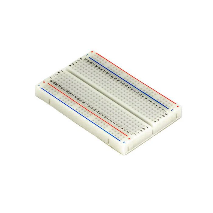 |
| Jumper wires | 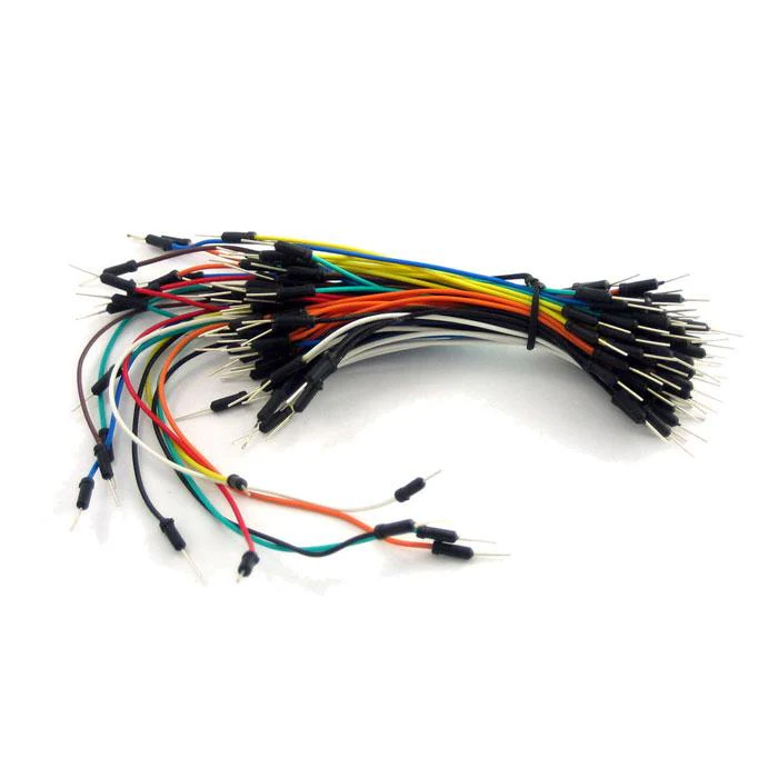 |
| Arduino Uno R4 Minima | 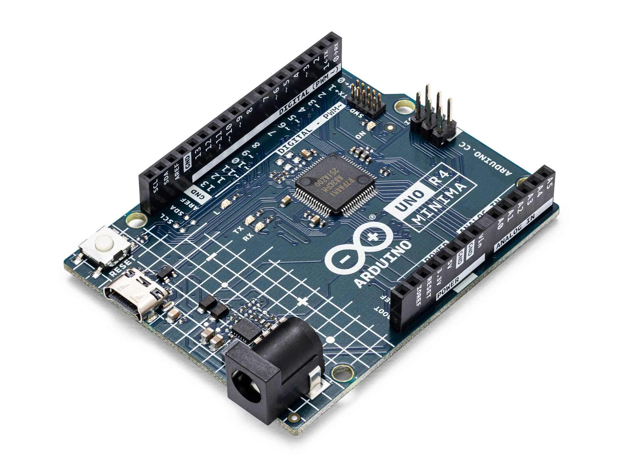 |
| 3-6V Motor with Fan Blade | 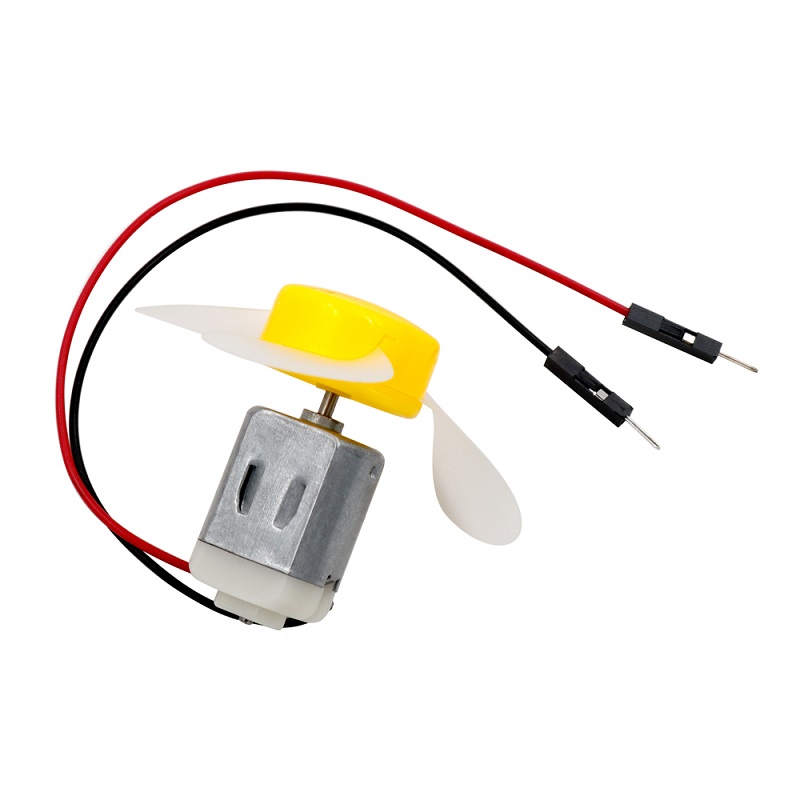 |
| L293D Motor Driver |  |
Instructions
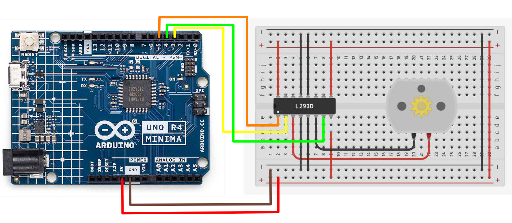
- Make the following connections using the breadboard and jumper wires.
L293D Pin Configuration
- Vcc1 (Pin 16): Connect to 5V from the Arduino.
- Vcc2 (Pin 8): Connect to 5V from the Arduino.
- ENABLE1 (Pin 1): Connect to the Arduino pin defined as ENABLE (Pin 5 in the code).
- INPUT1 (Pin 2): Connect to the Arduino pin defined as DIRA (Pin 3 in the code).
- INPUT2 (Pin 7): Connect to the Arduino pin defined as DIRB (Pin 4 in the code).
- EN 2 (Pin 9): Connect to 5V from the Arduino.
Arduino to L293D:
- GND: Connect to L293D Pins 4, 5, 12, and 13 (GND).
Motor Connections:
- Connect one terminal of the motor to L293D Pin 3 (OUTPUT1).
- Connect the other terminal of the motor to Pin 6 (OUTPUT2)
- Paste the following code into your main Arduino sketch:
Code
#define ENABLE 5
#define DIRA 3
#define DIRB 4

int i;

void setup() {
  //---set pin direction
  pinMode(ENABLE,OUTPUT);
  pinMode(DIRA,OUTPUT);
  pinMode(DIRB,OUTPUT);
  Serial.begin(9600);
}

void loop() {
  //---back and forth example
    Serial.println("One way, then reverse");
    digitalWrite(ENABLE,HIGH); // enable on
    for (i=0;i<5;i++) {
    digitalWrite(DIRA,HIGH); //one way
    digitalWrite(DIRB,LOW);
    delay(500);
    digitalWrite(DIRA,LOW);  //reverse
    digitalWrite(DIRB,HIGH);
    delay(500);
  }
  digitalWrite(ENABLE,LOW); // disable
  delay(2000);

  Serial.println("fast Slow example");
  //---fast/slow stop example
  digitalWrite(ENABLE,HIGH); //enable on
  digitalWrite(DIRA,HIGH); //one way
  digitalWrite(DIRB,LOW);
  delay(3000);
  digitalWrite(ENABLE,LOW); //slow stop
  delay(1000);
  digitalWrite(ENABLE,HIGH); //enable on
  digitalWrite(DIRA,LOW); //one way
  digitalWrite(DIRB,HIGH);
  delay(3000);
  digitalWrite(DIRA,LOW); //fast stop
  delay(2000);

  Serial.println("PWM full then slow");
  //---PWM example, full speed then slow
  analogWrite(ENABLE,255); //enable on
  digitalWrite(DIRA,HIGH); //one way
  digitalWrite(DIRB,LOW);
  delay(2000);
  analogWrite(ENABLE,180); //half speed
  delay(2000);
  analogWrite(ENABLE,128); //half speed
  delay(2000);
  analogWrite(ENABLE,50); //half speed
  delay(2000);
  analogWrite(ENABLE,128); //half speed
  delay(2000);
  analogWrite(ENABLE,180); //half speed
  delay(2000);
  analogWrite(ENABLE,255); //half speed
  delay(2000);
  digitalWrite(ENABLE,LOW); //all done
  delay(10000);
}
-
Connect your Arduino to your laptop using a USB-C cable and upload the code to the arduino.
-
Test! Watch the DC motor run in different directions and speed. Ensure that the code is functioning properly with the serial monitor print statements.
Relay
Do not change any wiring for the next steps.
- Open the Arduino IDE and paste the following code into your main Arduino Sketch.
#define ENABLE 5
#define DIRA 3
#define DIRB 4

int i;

void setup() {
  //---set pin direction
  pinMode(ENABLE, OUTPUT);
  pinMode(DIRA, OUTPUT);
  pinMode(DIRB, OUTPUT);
  Serial.begin(9600);
}

void loop() {

  //---relay example
  digitalWrite(ENABLE, HIGH); // enable on
  for (i = 0; i < 5; i++)
  {
    Serial.println("spin");
    digitalWrite(DIRA, HIGH); //motor spins
    digitalWrite(DIRB, LOW);
    delay(2000);
    Serial.println("stop");
    digitalWrite(DIRA, LOW); //motor stops
    digitalWrite(DIRB, HIGH);
    delay(2000);
  }
}
- Repeat Steps 3 and 4.
| Prev | Next |
|---|---|
| 25. Shift Registers and 4 Digit Display | 27. Stepper Motor |