2. Digital Input
This will teach you about digital inputs using buttons and LEDs. This is really important for user input interactions, sensors, and communication!
Materials
| Component | Image |
|---|---|
| Breadboard | 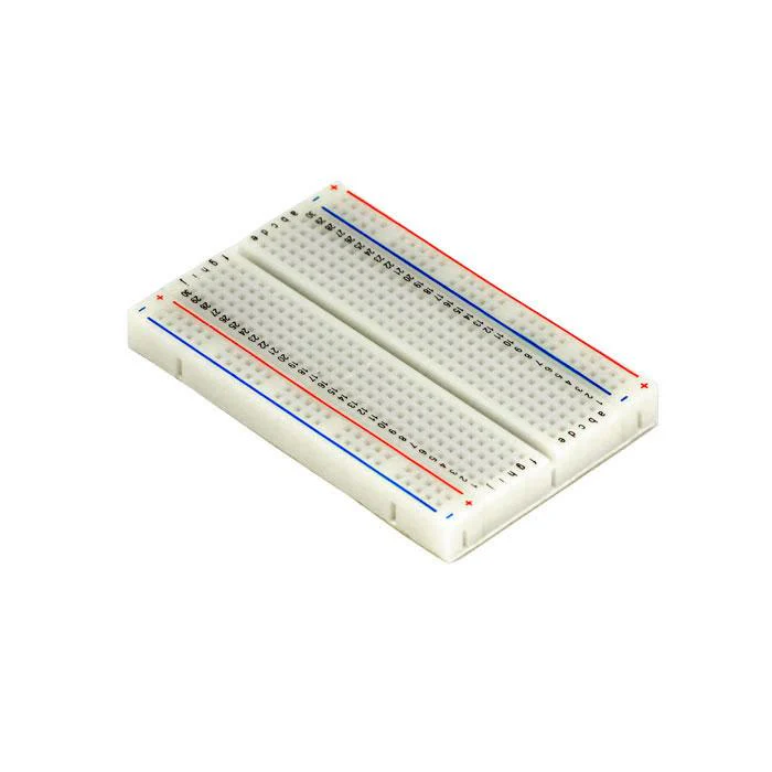 |
| Jumper wires | 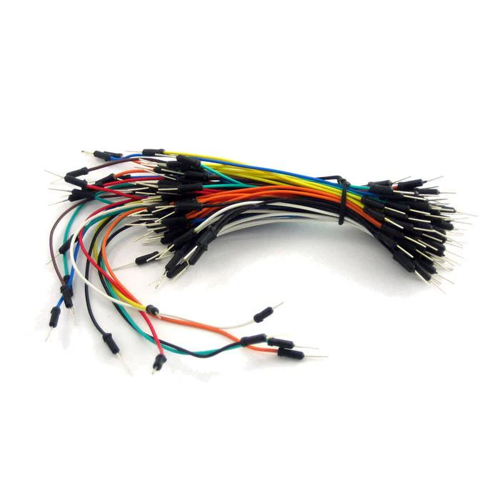 |
| Arduino Uno R4 Minima | 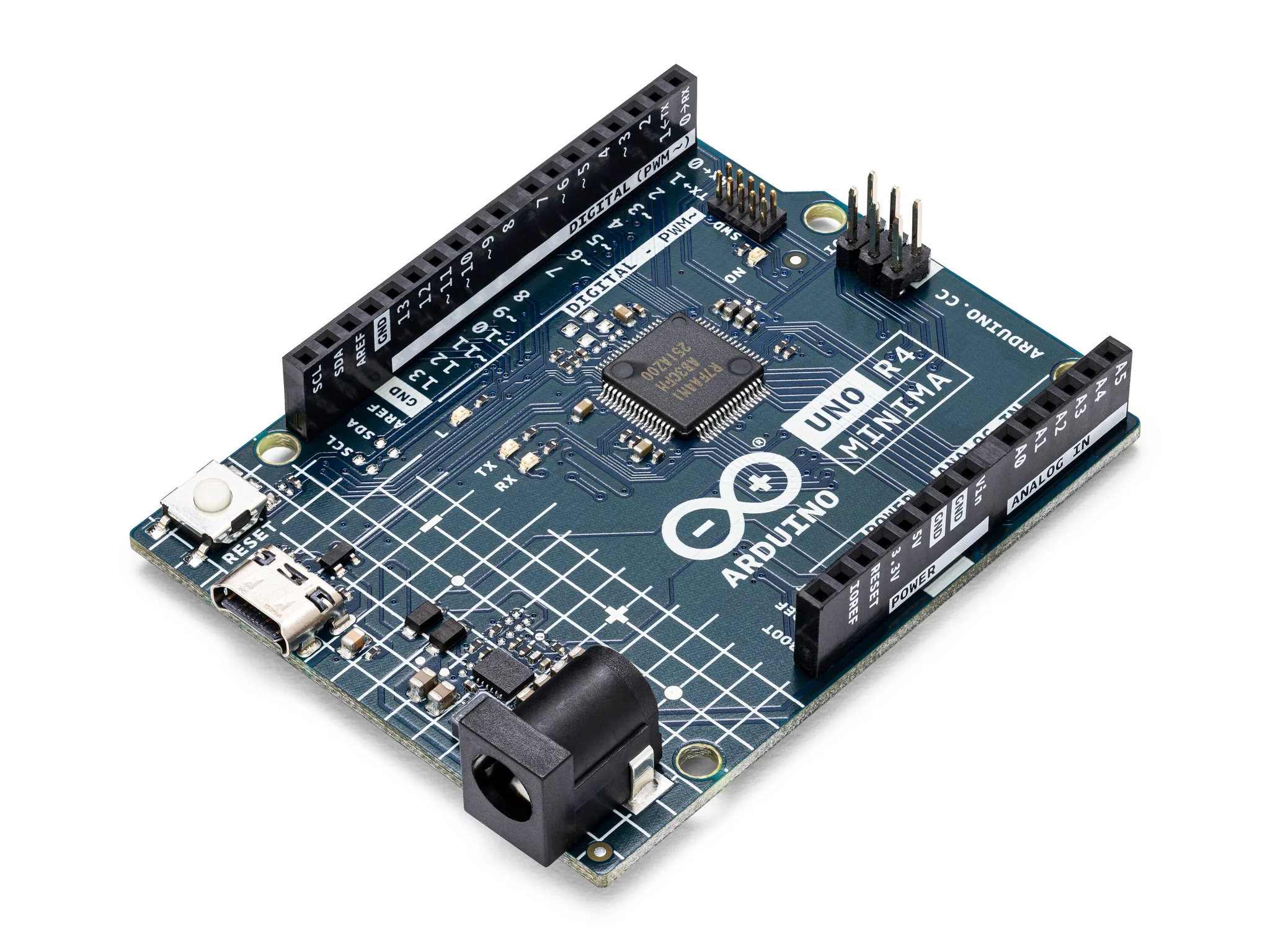 |
| LED (white, red, blue, or green) | 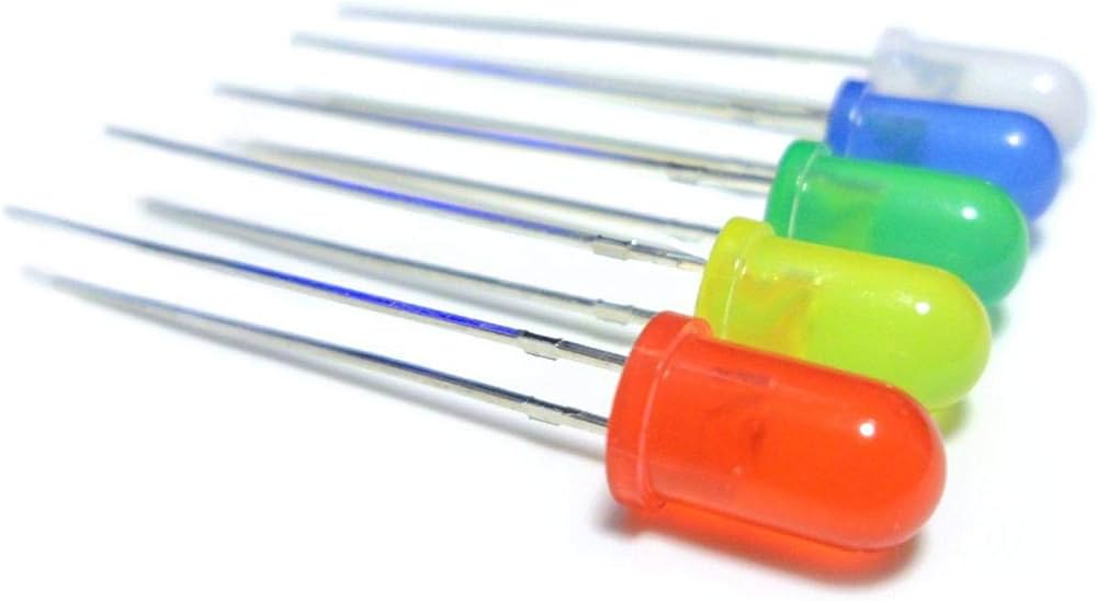 |
| Resistor (220 ohms for the LED, optional if using internal pull-up resistors for buttons) | 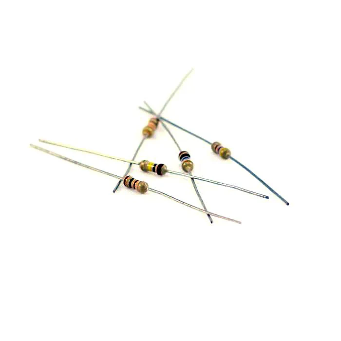 |
| 2 push buttons | 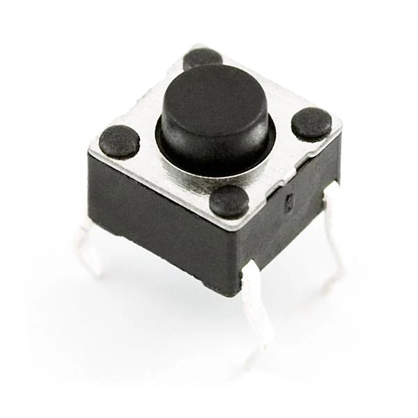 |
Instructions
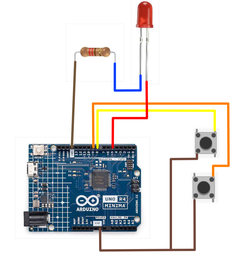
- Make the following connections using the jumper wires:
Connections
- LED: Connect the anode (longer leg) to digital pin 5 and the cathode (shorter leg) to ground through a 220-ohm resistor.
- Button A: Connect one leg to digital pin 9 and the other leg to ground.
- Button B: Connect one leg to digital pin 8 and the other leg to ground.
- Once wired, upload the following code to your Arduino IDE:
Code
int ledPin = 5;
int buttonApin = 9;
int buttonBpin = 8;

void setup() {
  pinMode(ledPin, OUTPUT);
  pinMode(buttonApin, INPUT_PULLUP);
  pinMode(buttonBpin, INPUT_PULLUP);
}

void loop() {
  if (digitalRead(buttonApin) == LOW) {
    digitalWrite(ledPin, HIGH);
    Serial.println("ON");
  } else if (digitalRead(buttonBpin) == LOW) {
    digitalWrite(ledPin, LOW);
    Serial.println("OFF");
  }
}
- Test! Play around with the buttons and customize the digital inputs.
| Prev | Next |
|---|---|
| 1. RGB LED Module | 3. Making Sounds |