22. The Serial Monitor
Shift registers are versatile components that allow you to control multiple outputs using only a few pins from your microcontroller. This is particularly useful when you need to control many LEDs but have limited I/O pins available on your Arduino.
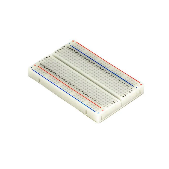
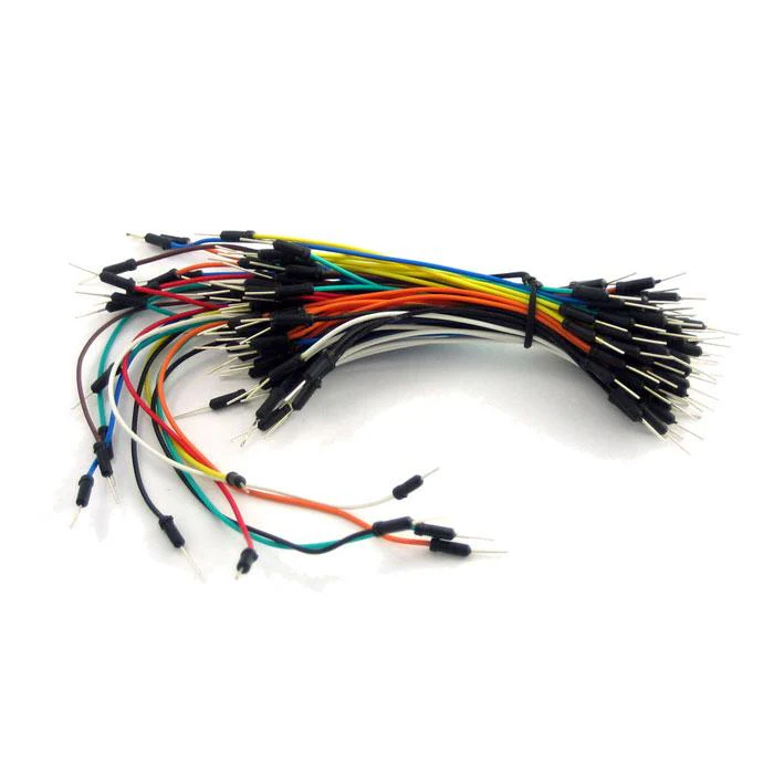
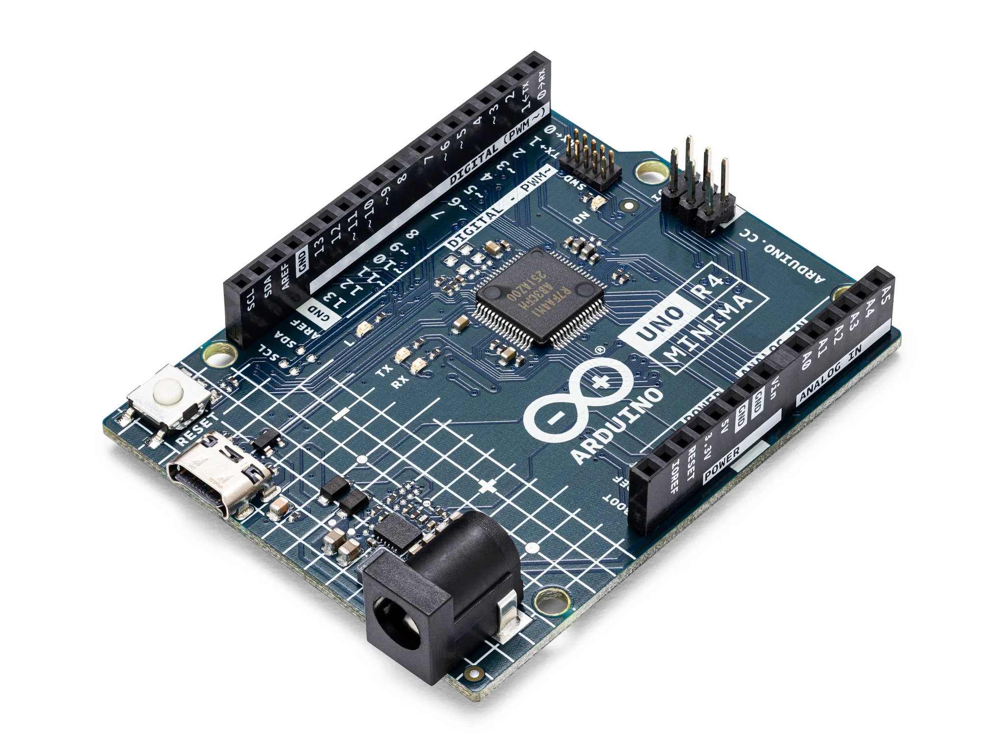
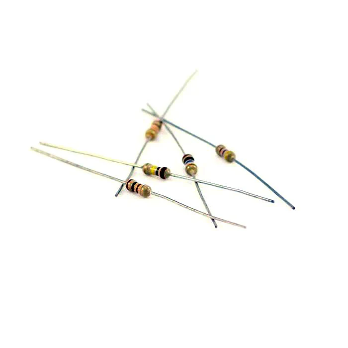
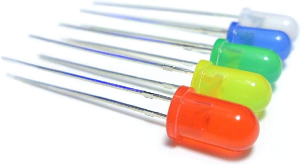
Materials
Instructions
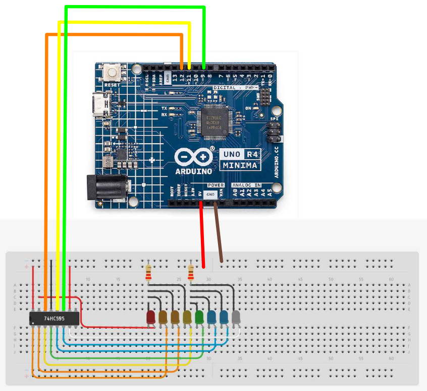
- Make the following connections using the breadboard and jumper wires.
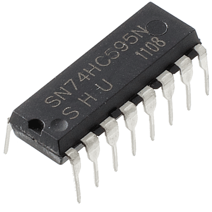
74HC595 Shift Register Pins:
- Pin 11 (SRCLR): Connect to 5V (to keep the shift register clear).
- Pin 12 (RCLK / Latch Pin): Connect to Arduino R4 pin 11.
- Pin 14 (SER / Data Pin): Connect to Arduino R4 pin 12.
- Pin 10 (SRCLK / Clock Pin): Connect to Arduino R4 pin 9.
- Pin 8 (GND): Connect to ground.
- Pin 16 (VCC): Connect to 5V.
- Pin 13 (OE): Connect to ground (to enable output).
LEDs and Resistors:
- Connect the positive legs of the LEDs to the output pins Q0 to Q7 of the 74HC595.
- Connect the negative legs of the LEDs to ground through the current-limiting resistors.
- Paste the following code into your main Arduino sketch:
Code
int latchPin = 11;
int clockPin = 9;
int dataPin = 12;

byte leds = 0;

void updateShiftRegister()
{
   digitalWrite(latchPin, LOW);
   shiftOut(dataPin, clockPin, LSBFIRST, leds);
   digitalWrite(latchPin, HIGH);
}

void setup()
{
  pinMode(latchPin, OUTPUT);
  pinMode(dataPin, OUTPUT);
  pinMode(clockPin, OUTPUT);
  updateShiftRegister();
  Serial.begin(9600);
  while (! Serial); // Wait until Serial is ready - Leonardo
  Serial.println("Enter LED Number 0 to 7 or 'x' to clear");
}

void loop()
{
  if (Serial.available())
  {
    char ch = Serial.read();
    if (ch >= '0' && ch <= '7')
    {
      int led = ch - '0';
      bitSet(leds, led);
      updateShiftRegister();
      Serial.print("Turned on LED ");
      Serial.println(led);
    }
    if (ch == 'x')
    {
      leds = 0;
      updateShiftRegister();
      Serial.println("Cleared");
    }
  }
}
-
Connect your Arduino to your laptop using a USB-C cable and upload the code to the arduino.
-
Test! Very the inputs into your serial monitor and observe the light changes.
| Prev | Next |
|---|---|
| 21. Shift Registers and LED | 23. Photocell |