21. Shift Registers and LED
description
Materials
| Component | Image |
|---|---|
| Breadboard | 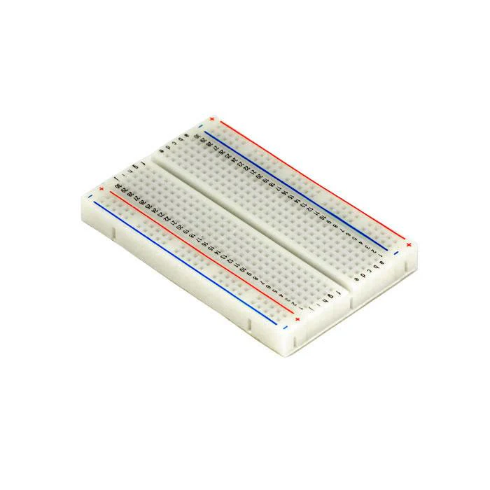 |
| Jumper wires | 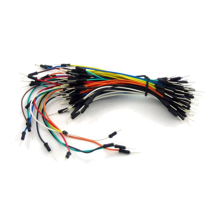 |
| Arduino Uno R4 Minima | 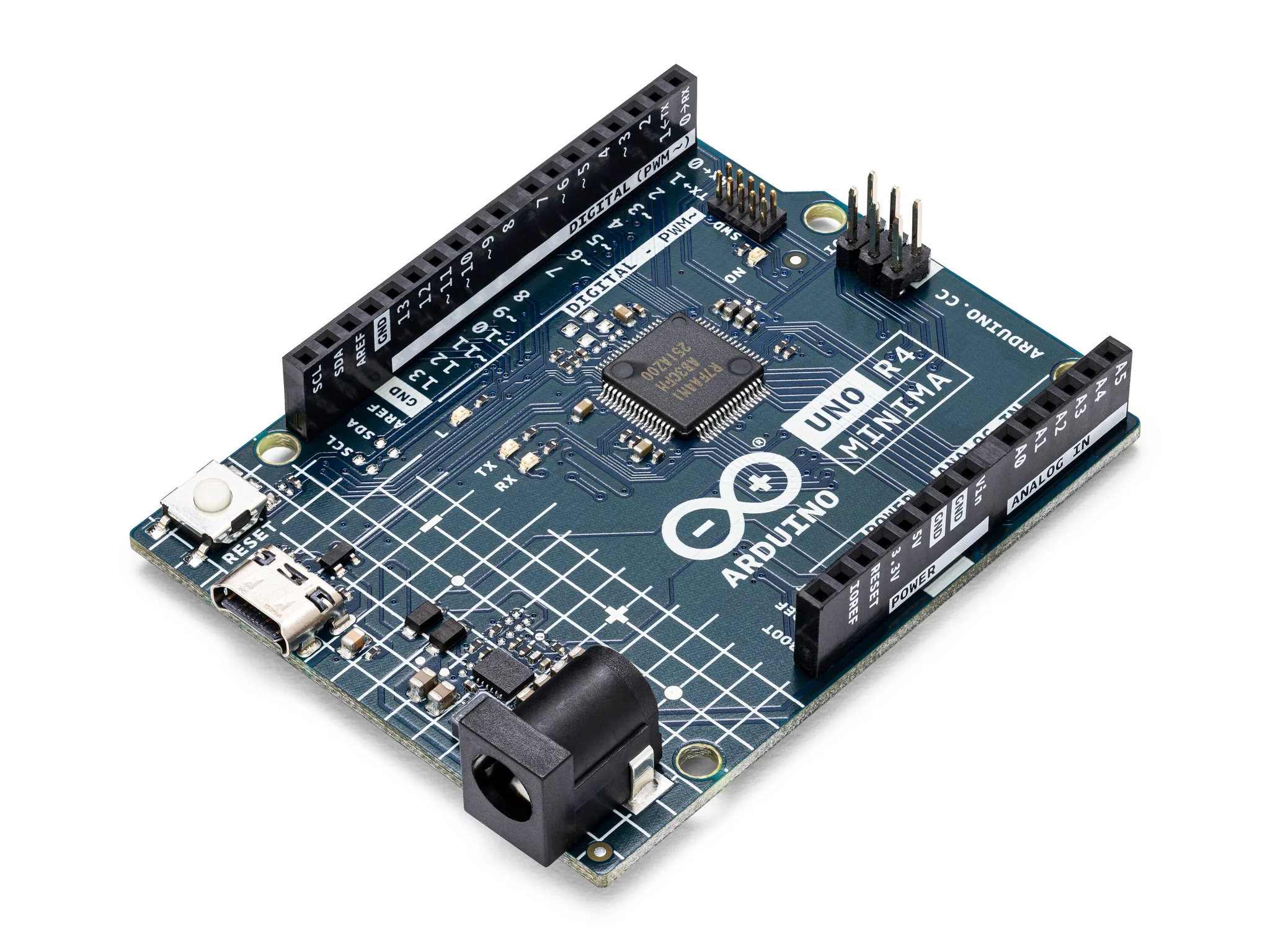 |
| 74HC595 Shift Register | 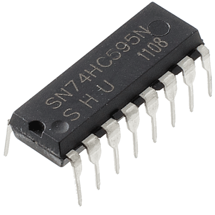 |
| LED (white, red, blue, or green) |  |
Instructions
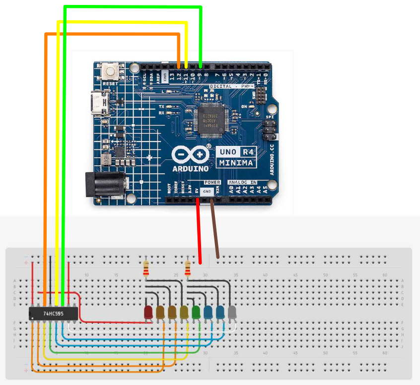
- Make the following connections using the breadboard and jumper wires.
Power Connections
- Pin 16 of the 74HC595 to 5V.
- Pin 8 of the 74HC595 to the GND.
Control Pin Connections
- Connect Pin 11 (SH_CP) of the 74HC595 to Pin 9 on the Arduino.
- Connect Pin 12 (ST_CP) of the 74HC595 to Pin 11 on the Arduino.
- Connect Pin 14 (DS) of the 74HC595 to Pin 12 on the Arduino.
- Connect Pin 13 (OE) of the 74HC595 to the GND rail.
- Connect Pin 10 (MR) of the 74HC595 to the 5V rail.
LED Connections:
- Connect Pin 15 (Q0) to the anode of the first LED.
- Connect Pin 1 (Q1) to the anode of the second LED.
- Connect Pin 2 (Q2) to the anode of the third LED.
- Connect Pin 3 (Q3) to the anode of the fourth LED.
- Connect Pin 4 (Q4) to the anode of the fifth LED.
- Connect Pin 5 (Q5) to the anode of the sixth LED.
- Connect Pin 6 (Q6) to the anode of the seventh LED.
- Connect Pin 7 (Q7) to the anode of the eighth LED.
- Connect the cathode of each LED to one end of a 220 ohm resistor.
- Connect the other end of each resistor to the GND rail on the breadboard.
- Paste the following code into your main Arduino sketch:
Code
int tDelay = 100;
int latchPin = 11;  // (11) ST_CP [RCK] on 74HC595
int clockPin = 9;   // (9) SH_CP [SCK] on 74HC595
int dataPin = 12;   // (12) DS [S1] on 74HC595

byte leds = 0;

void updateShiftRegister() {
  digitalWrite(latchPin, LOW);
  shiftOut(dataPin, clockPin, LSBFIRST, leds);
  digitalWrite(latchPin, HIGH);
}

void setup() {
  pinMode(latchPin, OUTPUT);
  pinMode(dataPin, OUTPUT);
  pinMode(clockPin, OUTPUT);
}

void loop() {
  leds = 0;
  updateShiftRegister();
  delay(tDelay);
  for (int i = 0; i < 8; i++) {
    bitSet(leds, i);
    updateShiftRegister();
    delay(tDelay);
  }
}
-
Connect your Arduino to your laptop using a USB-C cable and upload the code to the arduino.
-
Test! Observe the LEDs change sequentially.
| Prev | Next |
|---|---|
| 20. Thermometer | 22. The Serial Monitor |