24. Shift Registers and 7-Segment Display
The 74HC595 is an 8-bit serial-in, parallel-out shift register. This means it can take in a serial data input (one bit at a time) and then output the data in parallel (all 8 bits at once). This functionality is particularly useful for expanding the number of output pins available on a microcontroller. A 7-segment display is a simple electronic display device that can display digits from 0 to 9. It consists of seven LEDs (segments) arranged in a pattern that can form each digit. Each segment is labeled with a letter from 'a' to 'g'.
Materials
| Component | Image |
|---|---|
| Breadboard | 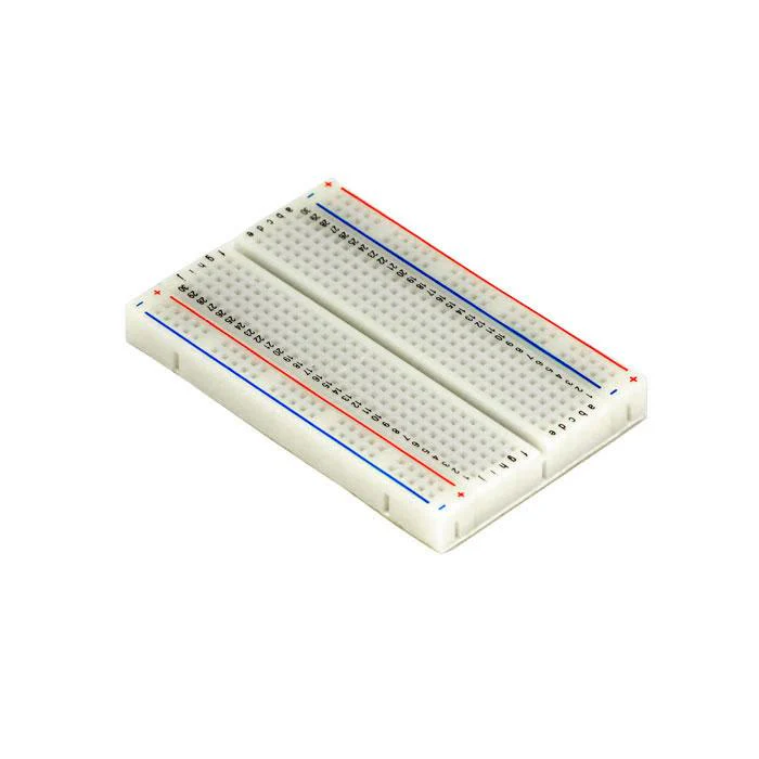 |
| Jumper wires | 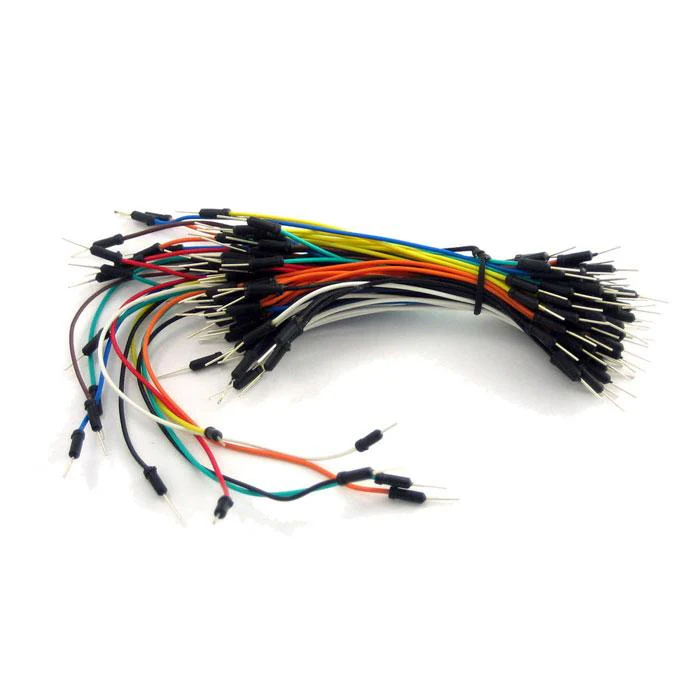 |
| Arduino Uno R4 Minima | 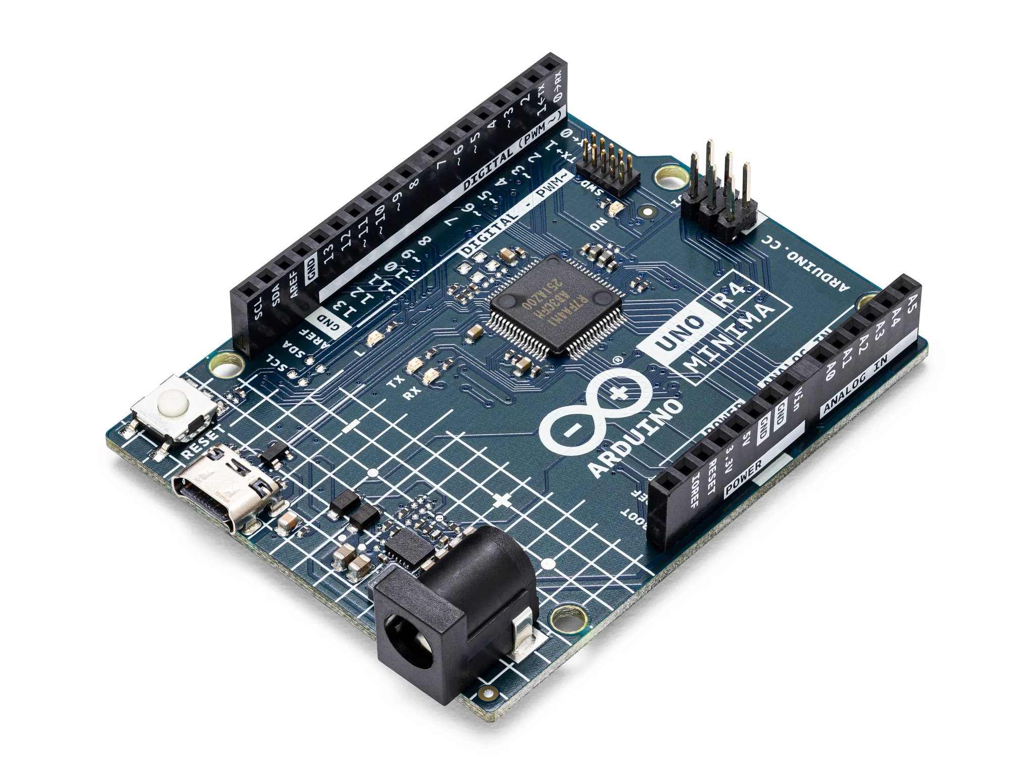 |
| Resistors (220 ohms for the LED, optional if using internal pull-up resistors for buttons) | 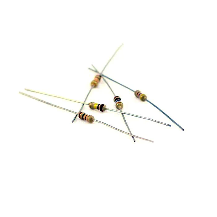 |
| 7 Segment Display | 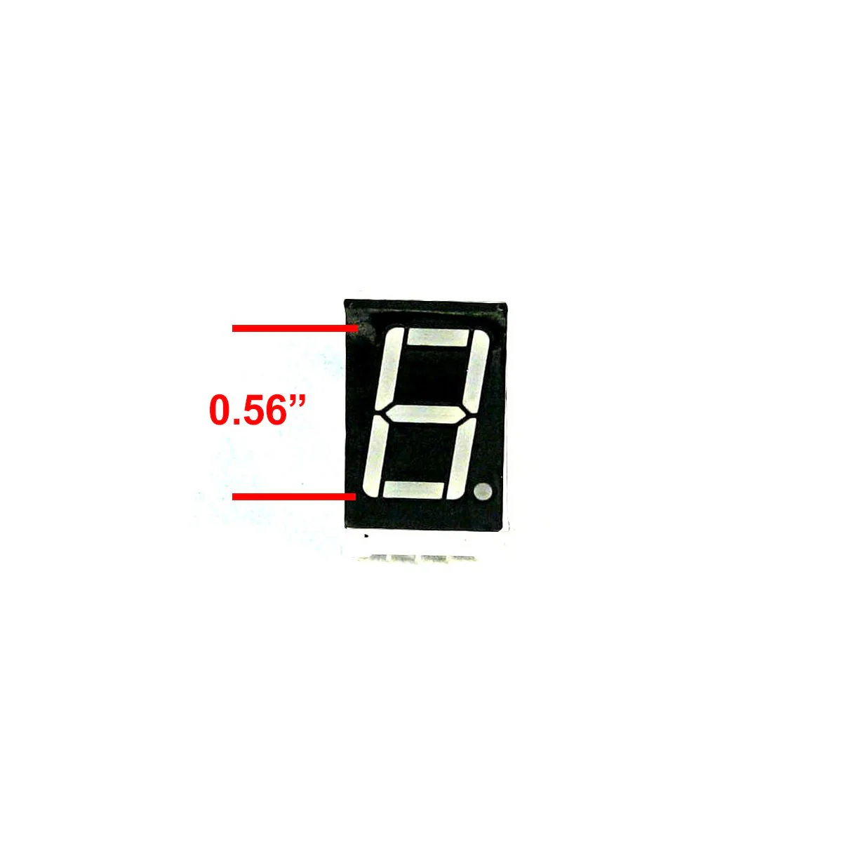 |
| 74HC595 Shift Register | 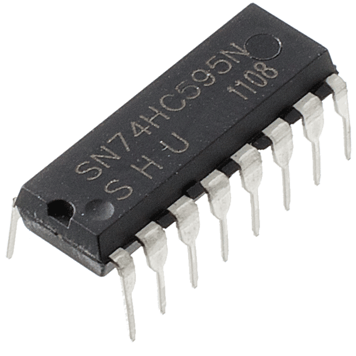 |
Instructions
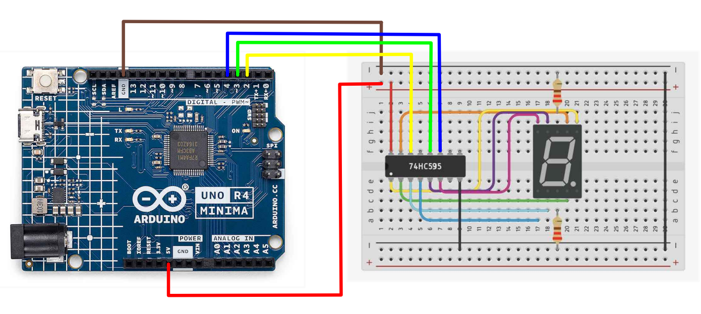
- Make the following connections using the breadboard and jumper wires.
74HC595 Shift Register Connections
- DS (Data Pin) to Arduino pin 2
- SH_CP (Clock Pin) to Arduino pin 4
- ST_CP (Latch Pin) to Arduino pin 3
- VCC to 5V on Arduino
- GND to GND on Arduino
7 Segment Display to Shift Register
- Q0 (Pin 15 on 74HC595): Connect to Segment A (Pin 10 on 7-segment display)
- Q1 (Pin 1 on 74HC595): Connect to Segment B (Pin 7 on 7-segment display)
- Q2 (Pin 2 on 74HC595): Connect to Segment C (Pin 4 on 7-segment display)
- Q3 (Pin 3 on 74HC595): Connect to Segment D (Pin 2 on 7-segment display)
- Q4 (Pin 4 on 74HC595): Connect to Segment E (Pin 1 on 7-segment display)
- Q5 (Pin 5 on 74HC595): Connect to Segment F (Pin 9 on 7-segment display)
- Q6 (Pin 6 on 74HC595): Connect to Segment G (Pin 5 on 7-segment display)
- Q7 (Pin 7 on 74HC595): Connect to Decimal Point (Pin 6 on 7-segment display)(optional)
- Paste the following code into your main Arduino sketch:
Code��
byte seven_seg_digits[10] = { B11111100,  // = 0
                              B01100000,  // = 1
                              B11011010,  // = 2
                              B11110010,  // = 3
                              B01100110,  // = 4
                              B10110110,  // = 5
                              B10111110,  // = 6
                              B11100000,  // = 7
                              B11111110,  // = 8
                              B11100110   // = 9
                             };


int latchPin = 3;

int clockPin = 4;

int dataPin = 2;

void setup() {
  Serial.begin(9600);
  pinMode(latchPin, OUTPUT);
  pinMode(clockPin, OUTPUT);
  pinMode(dataPin, OUTPUT);
}


void sevenSegWrite(byte digit) {
  digitalWrite(latchPin, LOW);
  shiftOut(dataPin, clockPin, LSBFIRST, seven_seg_digits[digit]);
  digitalWrite(latchPin, HIGH);
}

void loop() {

  for (byte digit = 10; digit > 0; --digit) {
    delay(1000);
    sevenSegWrite(digit - 1);
    Serial.println(digit - 1);
  }

  // suspend 4 seconds
  delay(3000);
}
-
Connect your Arduino to your laptop using a USB-C cable and upload the code to the arduino.
-
Test! Check to see if the numbers bring printed onto the serial monitor are corresponding to the numbers on the hex display.
| Prev | Next |
|---|---|
| 23. Photocell | 25. Shift Registers and 4 Digit Display |