25. Shift Registers and 4 Digit Display
7-segment displays are a popular choice for displaying numerical information in various electronic projects due to their simplicity and ease of use. By using a shift register, we can control multiple segments with just a few pins from the Arduino, making our project more efficient and allowing us to save precious I/O pins for other tasks.
Materials
Instructions
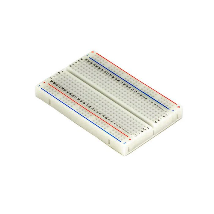
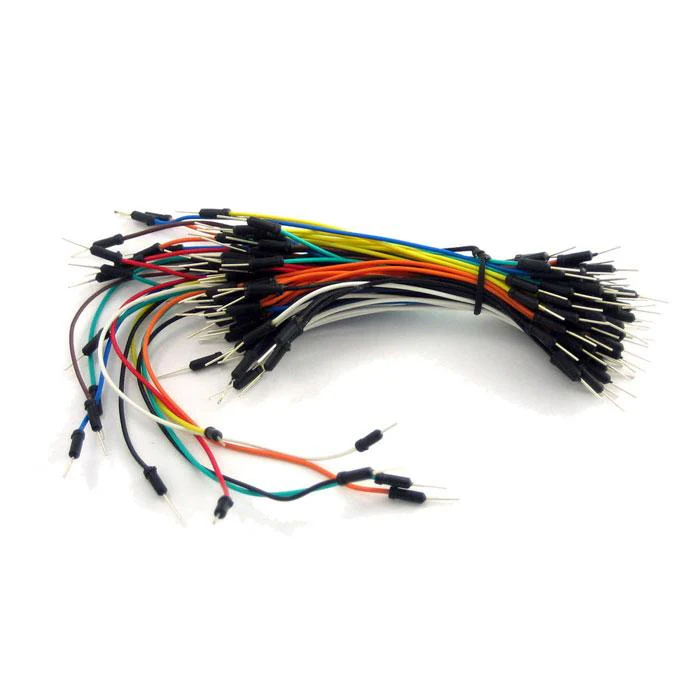
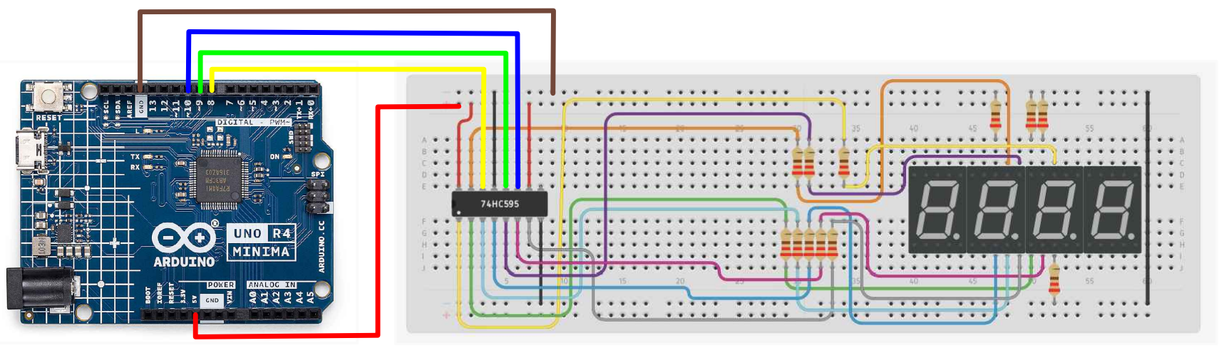
- Make the following connections using the breadboard and jumper wires.
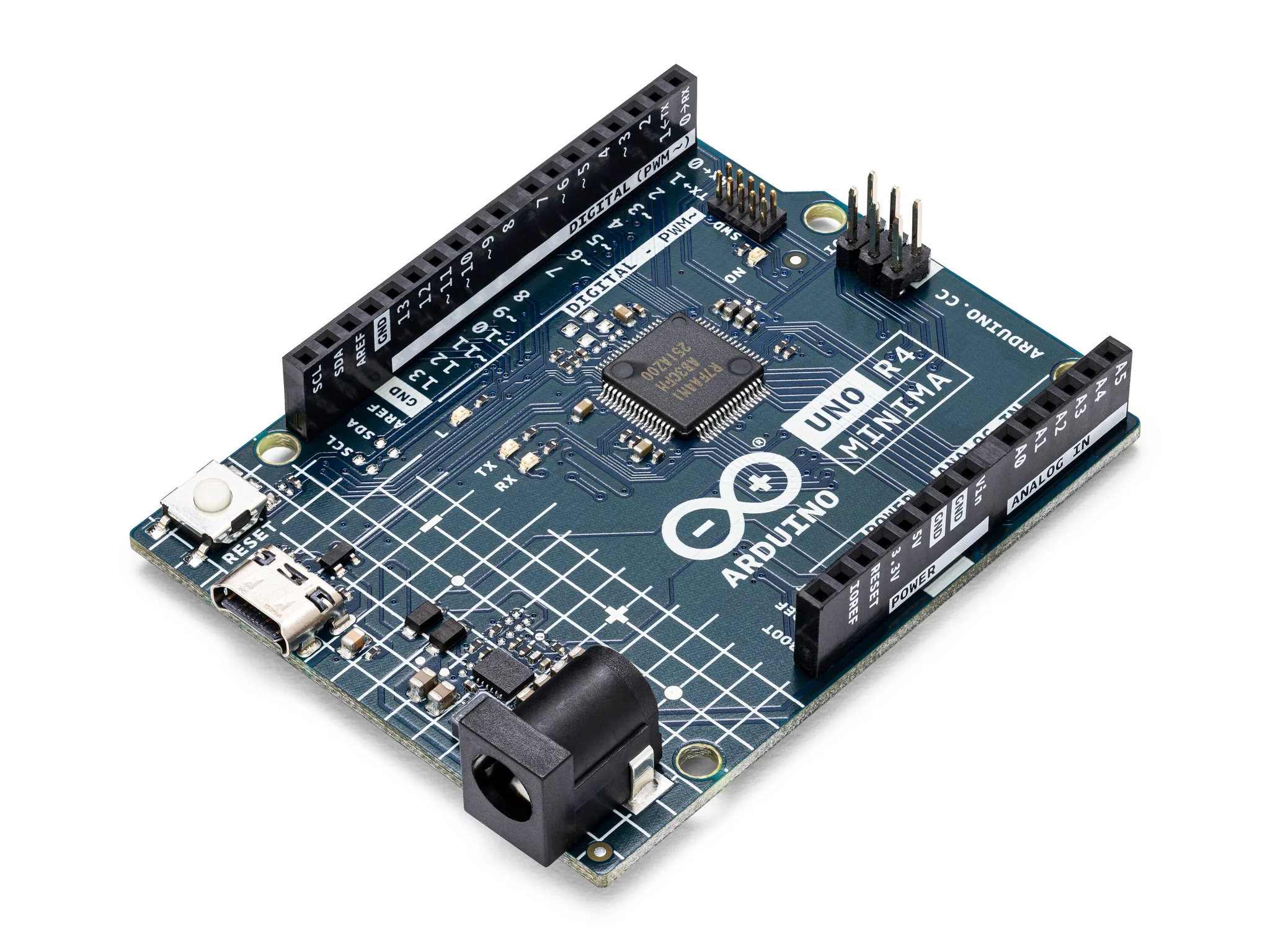
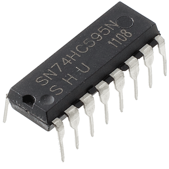
Arduino to 74HC595 Shift Register:
- Arduino Pin 9 (latch): Connect to ST_CP (Pin 12) on the 74HC595.
- Arduino Pin 10 (clock): Connect to SH_CP (Pin 11) on the 74HC595.
- Arduino Pin 8 (data): Connect to DS (Pin 14) on the 74HC595.
- 5V: Connect to VCC (Pin 16) on the 74HC595.
- GND: Connect to GND (Pin 8) on the 74HC595.
- GND: Connect to OE (Pin 13) on the 74HC595 to enable output.
- 5V: Connect to SRCLR (Pin 10) on the 74HC595 to disable clear function.
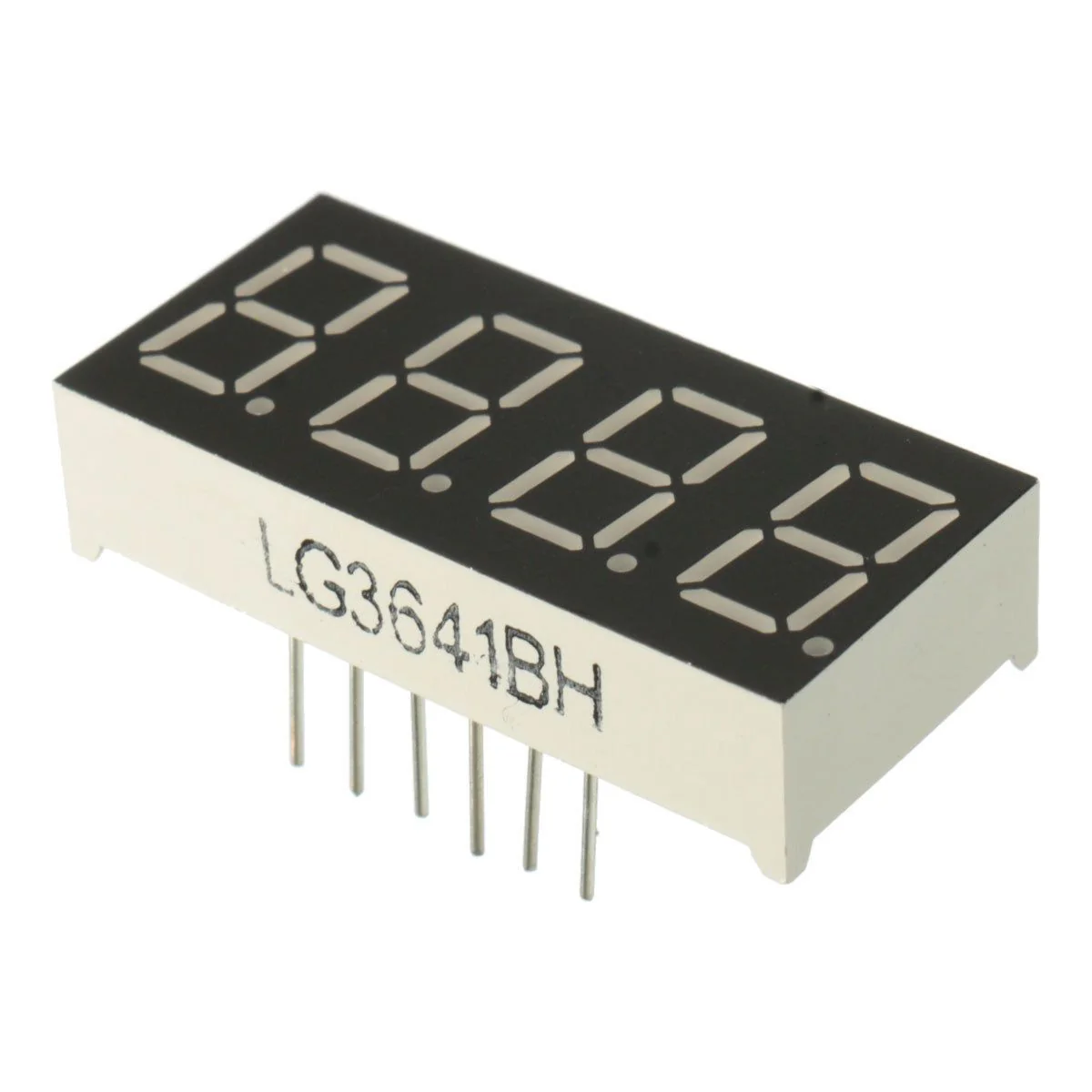
74HC595 to 7-Segment Display:
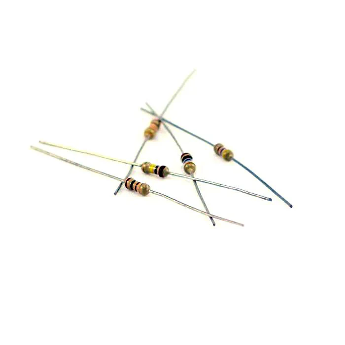
- Q0- (Pin 15 on 74HC595): Connect to Segment A of the 7-segment display through a 220-ohm resistor.
- Q1 (Pin 1 on 74HC595): Connect to Segment B of the 7-segment display through a 220-ohm resistor.
- Q2 (Pin 2 on 74HC595): Connect to Segment C of the 7-segment display through a 220-ohm resistor.
- Q3 (Pin 3 on 74HC595): Connect to Segment D of the 7-segment display through a 220-ohm resistor.
- Q4 (Pin 4 on 74HC595): Connect to Segment E of the 7-segment display through a 220-ohm resistor.
- Q5 (Pin 5 on 74HC595): Connect to Segment F of the 7-segment display through a 220-ohm resistor.
- Q6 (Pin 6 on 74HC595): Connect to Segment G of the 7-segment display through a 220-ohm resistor.
- Q7 (Pin 7 on 74HC595): Connect to the Decimal Point of the 7-segment display through a 220-ohm resistor (optional, depending on if you are using it).
Common Cathode Pins for Each Digit:
- Digit 1: Connect to Arduino Pin 2 through a 220-ohm resistor.
- Digit 2: Connect to Arduino Pin 3 through a 220-ohm resistor.
- Digit 3: Connect to Arduino Pin 4 through a 220-ohm resistor.
- Digit 4: Connect to Arduino Pin 5 through a 220-ohm resistor.
- Paste the following code into your main Arduino sketch:
Code
int latch=9;  //74HC595  pin 9 STCP
int clock=10; //74HC595  pin 10 SHCP
int data=8;   //74HC595  pin 8 DS

unsigned char table[]=
{0x3f,0x06,0x5b,0x4f,0x66,0x6d,0x7d,0x07,0x7f,0x6f,0x77,0x7c
,0x39,0x5e,0x79,0x71,0x00};

void setup() {
  pinMode(latch,OUTPUT);
  pinMode(clock,OUTPUT);
  pinMode(data,OUTPUT);
}
void Display(unsigned char num)
{

  digitalWrite(latch,LOW);
  shiftOut(data,clock,MSBFIRST,table[num]);
  digitalWrite(latch,HIGH);

}
void loop() {
  Display(1);
  delay(500);
  Display(2);
  delay(500);
  Display(3);
  delay(500);
  Display(4);
  delay(500);
  Display(5);
  delay(500);
  Display(6);
  delay(500);
  Display(7);
  delay(500);
  Display(8);
  delay(500);
  Display(9);
  delay(500);
  Display(10);
  delay(500);
  Display(11);
  delay(500);
  Display(12);
  delay(500);
  Display(13);
  delay(500);
  Display(14);
  delay(500);
  Display(15);
  delay(500);
}
-
Connect your Arduino to your laptop using a USB-C cable and upload the code to the arduino.
-
Test! Run the code and see if the correct numbers are displayed on the 4 digit 7 segment display.
| Prev | Next |
|---|---|
| 24. Shift Registers and 7 Segment Display | 26. DC Motor and Relay |