Project 5.2: One-way Data Communication - LED Control
Overview:
Project 5.2 is about setting up a firmware utilizing the ESP32’s capabilities for wireless communication. This project will guide you how to control RGB LEDs via UDP communications. The firmware is designed to respond to remote commands that adjust LED colors based on received inputs, providing an immediate visual presentation of the data on the TFT display. Previously, we set up a client on the computer, you can reuse the same client.cpp but you can also use Package Sender as a client.
Materials:
| Component | Image |
|---|---|
| 1.8" TFT LCD Screen | 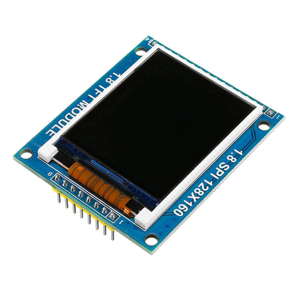 |
| 330 Ω Resistors | 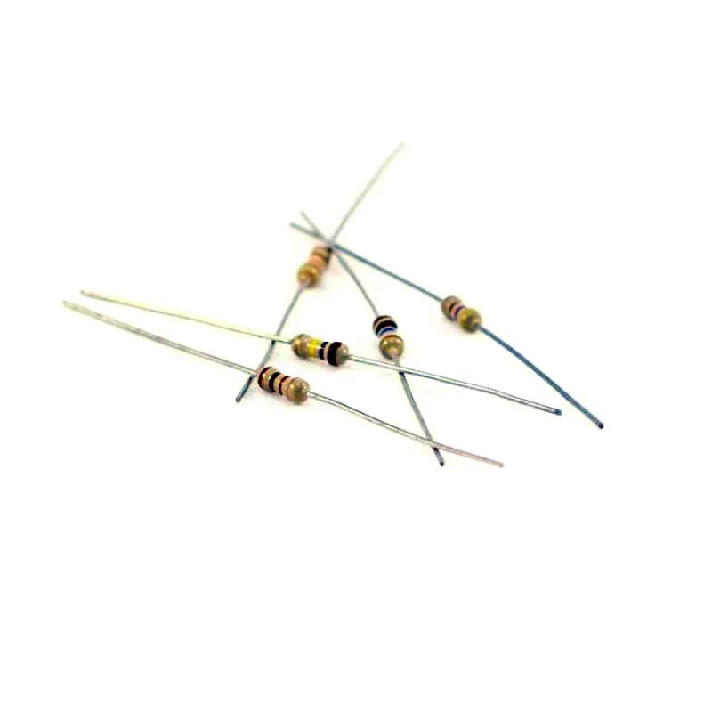 |
| RGB LED | 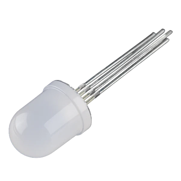 |
| ESP32 Dev Board | 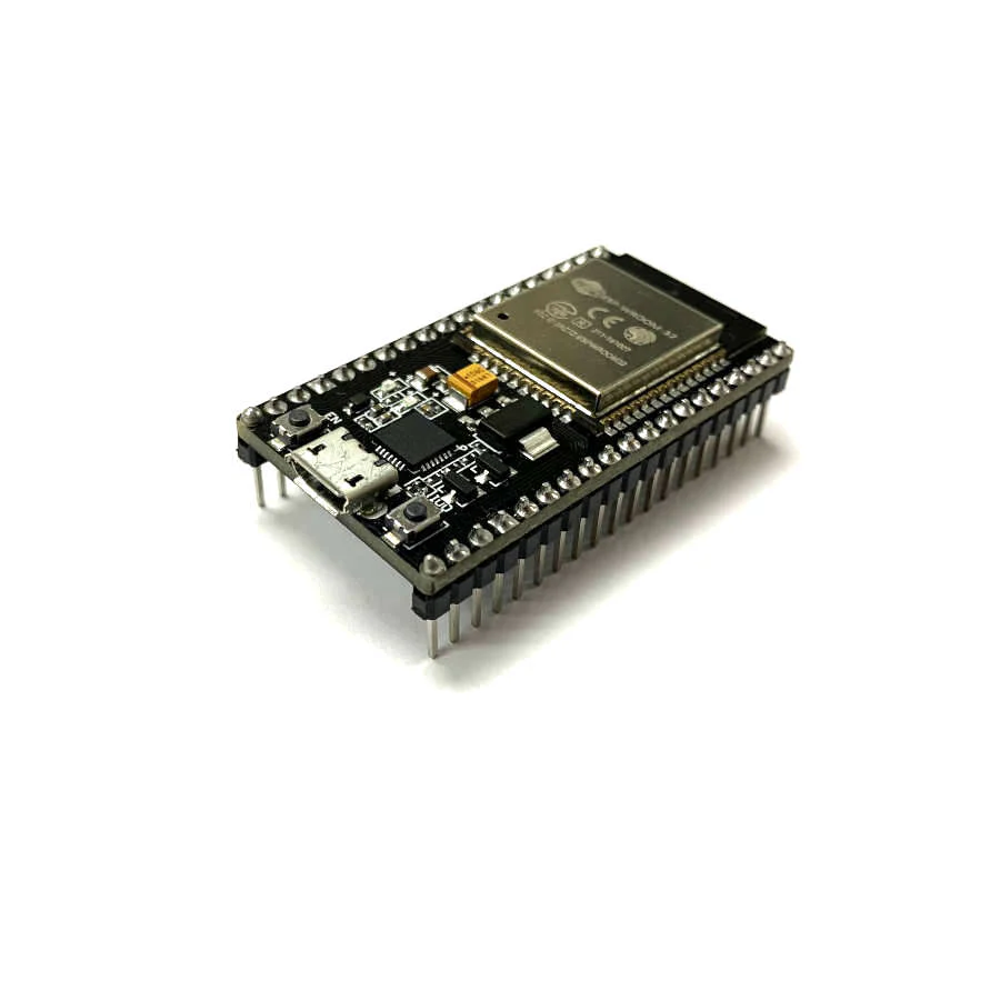 |
Objectives:
- Establish UDP communication: Implement a UDP server on the ESP32 that can receive color control commands from a remote client
- Enhance Visual Interaction: Utilize an ST7735 TFT display to provide feedback on the received commands and display the message on the screen
- Dynamic LED Control: Develop a system where RGB LEDs change color based on the commands received via the UDP network.
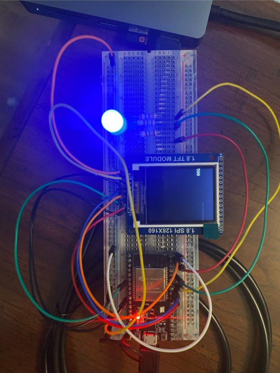
Hardware Assembly:
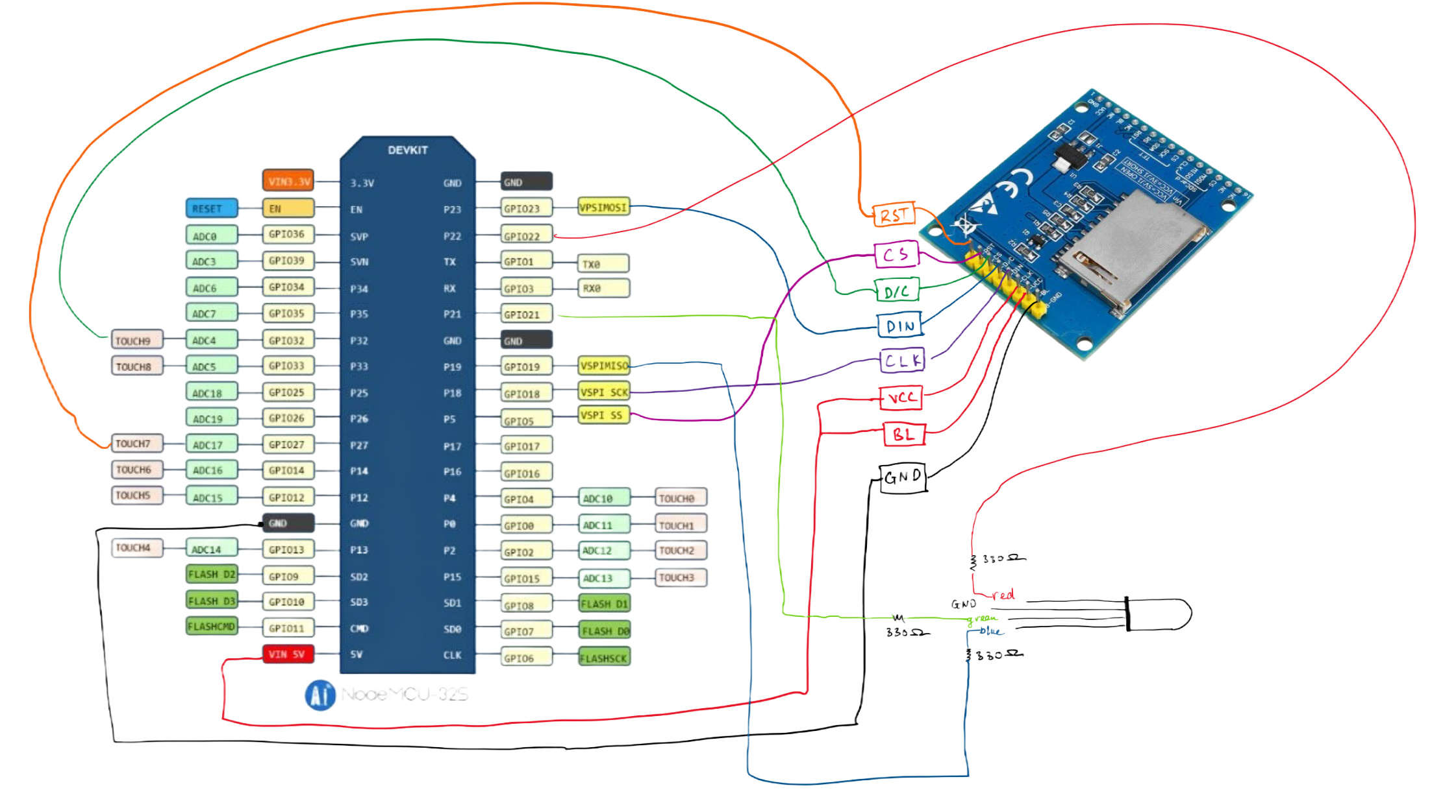
Pin Connection:
| Color | To ESP32 Pin |
|---|---|
| RED | P22 |
| GND | GND |
| GREEN | P21 |
| BLUE | P19 |
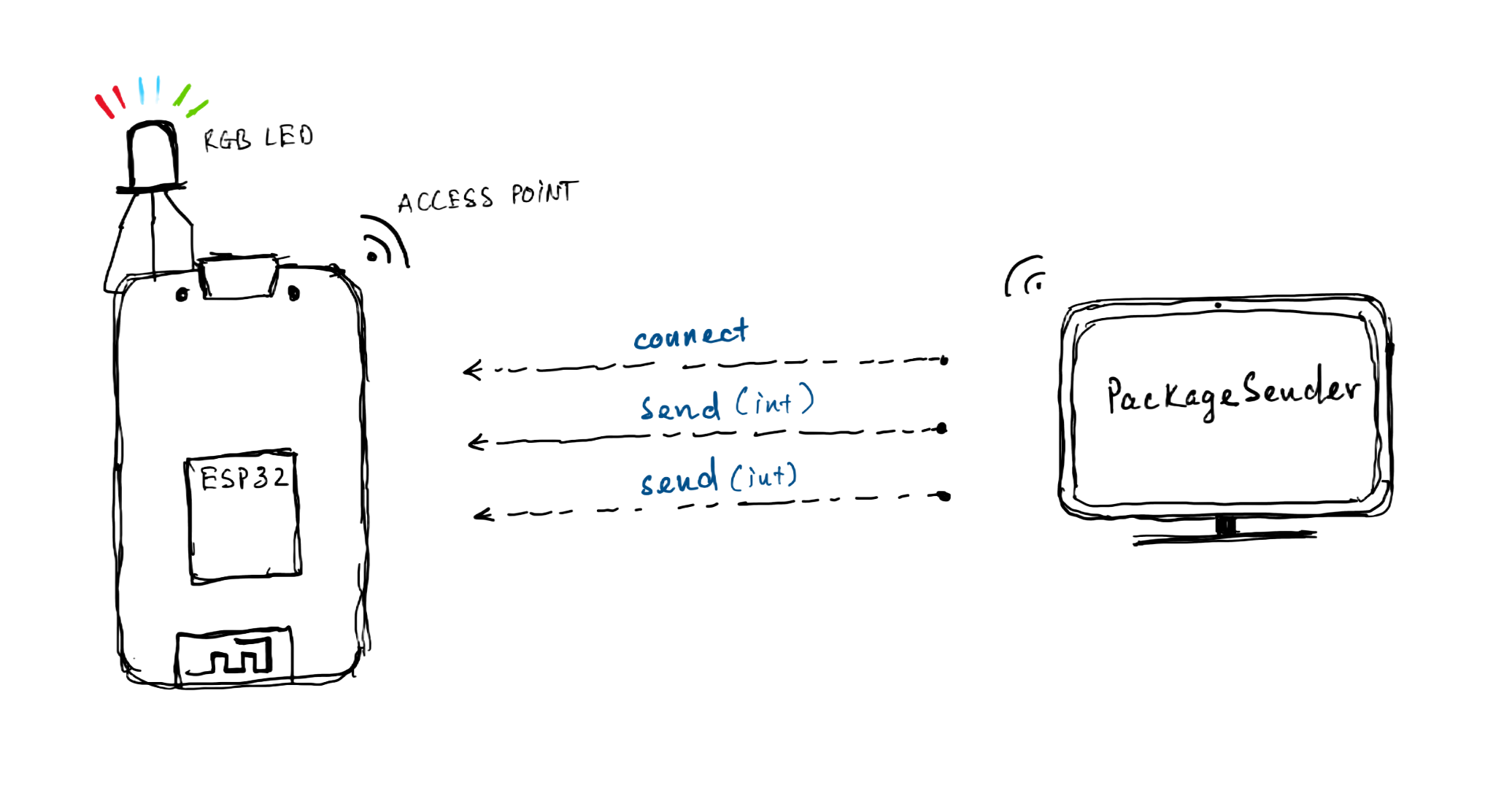
Network Diagram
Pseudocode:
ESP32
Declare necessary libraries and define pins
Initialize TFT display settings
Initialize WiFi as Access Point
Print IP Address and UDP port on TFT display
Set up UDP communication
Configure LED pins and perform initial LED blinking sequence
In the main loop:
    Check for incoming UDP packets
    If a packet is received:
        Read and display the packet content on the TFT display
        Convert the received string to an integer and set the LED color

Define setColor function:
    Calculate color intensities based on the input value
    Set the LED to the calculated color intensities
    Wait for 5 seconds before the next change
Instructions:
- Download and install Package Sender.
- Visit this repository and download project5_2.ino
- In project5_2.ino, you can change the name and password of the access point. Afterward, upload the code into the ESP32. If you don’t have a battery for the ESP32, then you can use your computer as a power souce for the ESP32.
- The IP address of the ESP32 should be there on the TFT screen, so note it down because this will be used as an address that your message will be sent to.
- Open Package Sender and connect your computer with the name of your access point or “ESP32-Access-point” as default. In Package Sender, you need to write an integer value under ASCII section, you copy the address and the port displayed on TFT screen and then put them under address and port section. Because we set up the ESP32 to accept UDP packet, we should set it to UDP in PackageSender and then press send. To be more illustrative, an picture is provided below:
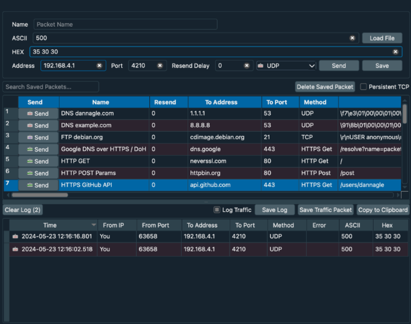
What you should see: