Tutorial: Building a Robot with Real-Time Temperature Display
In this tutorial, we will guide you through the process of building a robot that moves around and displays real-time temperature on a screen. By following the step-by-step instructions, you will learn how to assemble the necessary components, wire them together, and program the robot using Arduino IDE. Let's get started!


Materials
To build this robot, you will need the following components:
- ESP WROOM 32
- AM2320 Temperature Sensor
- 0.96-inch I2C OLED Display
- L293D Motor Controller
- Rounded Robot Chassis
- BreadBoard
- Jumper wires
- 6-AA Battery Holder
- Panasonic Battery AA (4-pack)
- Arduino IDE
Wiring & Setup
Connect the components according to the following wiring diagram:

Below are some of the pinouts:
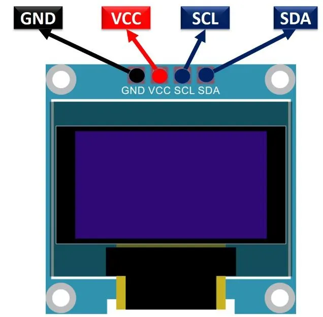
I2C OLED Pinout
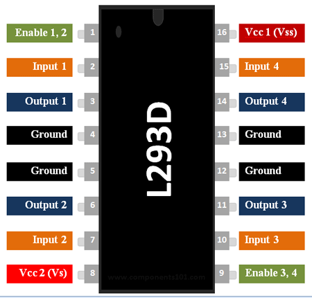
L293D Pinout
Step 1: Wiring Connections
The AM2320 temperature sensor is connected to an ESP-WROOM-32 microcontroller using the following pin configuration:
| AM2320 Temperature Sensor | ESP-WROOM-32 Pin |
|---|---|
| VCC | 3.3V |
| GND | GND |
| SDA | GPIO21 (SDA) |
| SCL | GPIO22 (SCL) |
The 0.96 Inch I2C OLED module is connected to an ESP-WROOM-32 microcontroller using the following pin configuration:
| 0.96 Inch I2C OLED Module | ESP-WROOM-32 Pin |
|---|---|
| VCC | 3.3V |
| GND | GND |
| SDA | GPIO21 (SDA) |
| SCL | GPIO22 (SCL) |
The L293D motor driver is connected to an ESP-WROOM-32 microcontroller using the following pin configuration:
| L293D Motor Driver | ESP-WROOM-32 Pin |
|---|---|
| IN1 | GPIO12 |
| IN2 | GPIO13 |
| IN3 | GPIO14 |
| IN4 | GPIO15 |
The first DC motor is connected to the motor driver using the following configuration:
| DC Motor 1 | Connection |
|---|---|
| Output 1 (OUT1) | Motor Driver |
| Output 2 (OUT2) | Motor Driver |
The second DC motor is connected to the motor driver using the following configuration:
| DC Motor 2 | Connection |
|---|---|
| Output 3 (OUT3) | Motor Driver |
| Output 4 (OUT4) | Motor Driver |
Step 2: Physical Assembly
1. Powering the ESP-WROOM-32:

-
Identify the VIN pin on the ESP-WROOM-32 module.
-
Connect the positive terminal (+) of the power supply to the VIN pin.
-
Connect the negative terminal (-) of the power supply to the GND pin of the ESP-WROOM-32.
2. Connect the motors to the L293D motor controller

** Note: you only need 1 ESP-wroom 32, this is to show how its wired. **
-
Find the IN1-IN4 pins on the L293D motor controller.
-
Connect Motor 1’s positive wire to OUT1 and negative wire to OUT2.
-
Connect Motor 2’s positive wire to OUT3 and negative wire to OUT4.
3. Connecting the AM2320 temperature sensor and 0.96 Inch I2C OLED :

Connect the VCC, GND, SDA, and SCL pins of the OLED module/Temp senosr to the corresponding pins on the ESP-WROOM-32.
- VCC to 3.3V power supply pin
- GND to GND pin
- SDA to GPIO21 (SDA) pin
- SCL to GPIO22 (SCL) pin.
4. Attach the wheels to the motor shafts:

-
Identify the motor shafts of Motors 1 and 2.
-
Attach the wheels securely to the motor shafts. Ensure they are aligned properly and tightly fixed to prevent slipping.
5. Put everything together:

- Place battery in the housing between the 2 brackets
- Place the ciruit on top
- Connect power
Step 3: Install Libraries
The libraries that are used are:
- Adafruit SSD1306 (Within IDE)
- Adafruit GFX Library (Within IDE)
- Adafruit BusIO (Within IDE)
- Adafruit AM2320 Sensor Library (Within IDE)
Click here for instructions to install libraries within the arduino application.
Step 4: Install Board
In order to interact with the ESP Wroom 32 Using the Arduino IDE, you must install the following board:
- ESP32 By Espressif (Within IDE)
Click here for instructions how to install boards within the arduino application.
Full Code
#include <Wire.h>
#include <Adafruit_AM2320.h>
#include <Adafruit_GFX.h>
#include <Adafruit_SSD1306.h>

#define SCREEN_WIDTH 128 // OLED display width, in pixels
#define SCREEN_HEIGHT 64 // OLED display height, in pixels

// Declaration for an SSD1306 display connected to I2C (SDA, SCL pins)
#define OLED_RESET     -1 // Reset pin # (or -1 if sharing Arduino reset pin)
Adafruit_SSD1306 display(SCREEN_WIDTH, SCREEN_HEIGHT, &Wire, OLED_RESET);

// Initialize the AM2320 sensor
Adafruit_AM2320 am2320 = Adafruit_AM2320();

// Initialize the motor driver pins
int motor1Pin1 = 12;
int motor1Pin2 = 13;
int motor2Pin1 = 14;
int motor2Pin2 = 15;

void setup() {
  // Start the serial communication
  Serial.begin(9600);

  // Initialize the OLED display
  if(!display.begin(SSD1306_SWITCHCAPVCC, 0x3C)) {
    Serial.println(F("SSD1306 allocation failed"));
    for(;;); // Don't proceed, loop forever
  }

  // Clear the screen
  display.clearDisplay();

  // Initialize the AM2320 sensor
  am2320.begin();

  // Initialize the motor driver pins as outputs
  pinMode(motor1Pin1, OUTPUT);
  pinMode(motor1Pin2, OUTPUT);
  pinMode(motor2Pin1, OUTPUT);
  pinMode(motor2Pin2, OUTPUT);
}

void loop() {
  // Read the temperature and humidity from the AM2320 sensor
  float temperature = am2320.readTemperature();

  // Display the temperature on the OLED display
  display.clearDisplay();
  display.setTextSize(1);
  display.setTextColor(SSD1306_WHITE);
  display.setCursor(0,0);
  display.print("Temperature:");
  display.setCursor(80,0);
  display.print(temperature);

  // Move the robot in a circle
  digitalWrite(motor1Pin1, HIGH);
  digitalWrite(motor1Pin2, LOW);

  digitalWrite(motor2Pin1, LOW);
  digitalWrite(motor2Pin2, HIGH);


   delay(2000);
}
Programming & Logic
Let's go through the logic of the code line by line:
- This code includes the necessary libraries for the I2C communication protocol, the AM2320 temperature and humidity sensor, the OLED display, and the motor driver.
#include <Wire.h>
#include <Adafruit_Sensor.h>
#include <Adafruit_AM2320.h>
#include <Adafruit_GFX.h>
#include <Adafruit_SSD1306.h>
- This code defines the screen width and height for the OLED display and initializes it.
#define SCREEN_WIDTH 128 // OLED display width, in pixels
#define SCREEN_HEIGHT 64 // OLED display height, in pixels

// Declaration for an SSD1306 display connected to I2C (SDA, SCL pins)
#define OLED_RESET     -1 // Reset pin # (or -1 if sharing Arduino reset pin)
Adafruit_SSD1306 display(SCREEN_WIDTH, SCREEN_HEIGHT, &Wire, OLED_RESET);
- Initialize the AM2320 temperature sensor object.
Adafruit_AM2320 am2320;
- This code initializes the pins for the L293D motor driver.
int motor1Pin1 = 12;
int motor1Pin2 = 13;
int motor2Pin1 = 14;
int motor2Pin2 = 15;
- This code initializes the serial communication, OLED display, AM2320 sensor and L293D motor driver pins as outputs.
 void setup() {
  // Start the serial communication
  Serial.begin(9600);

  // Initialize the OLED display
  if(!display.begin(SSD1306_SWITCHCAPVCC, 0x3C)) {
    Serial.println(F("SSD1306 allocation failed"));
    for(;;); // Don't proceed, loop forever
  }

  // Clear the screen
  display.clearDisplay();

  // Initialize the AM2320 sensor
  am2320.begin();

  // Initialize the motor driver pins as outputs
  pinMode(motor1Pin1, OUTPUT);
  pinMode(motor1Pin2, OUTPUT);
  pinMode(motor2Pin1, OUTPUT);
  pinMode(motor2Pin2, OUTPUT);
}
- This code reads the temperature from the AM2320 sensor and displays it on the OLED display. It also moves the robot in a circle by controlling the two DC motors using the L293D motor driver.
  void loop() {
  // Read the temperature and humidity from the AM2320 sensor
  float temperature = am2320.readTemperature();

  // Display the temperature on the OLED display
  display.clearDisplay();
  display.setTextSize(1);
  display.setTextColor(SSD1306_WHITE);
  display.setCursor(0,0);
  display.print("Temperature:");
  display.setCursor(80,0);
  display.print(temperature);

  // Move the robot in a circle
  digitalWrite(motor1Pin1, HIGH);
  digitalWrite(motor1Pin2, LOW);

  digitalWrite(motor2Pin1, LOW);
  digitalWrite(motor2Pin2, HIGH);


   delay(2000);
}
Troubleshooting
Hardware Tips
-
Battery: Ensure that you provide an adequate battery for your components. Check the power requirements of the motors, ESP32, OLED display, and other peripherals. Consider using separate power sources or using a power regulator to distribute power appropriately.
-
Wiring Connections: Double-check all your wiring connections to ensure they are secure and properly connected. Loose or incorrect connections can cause issues with functionality. Use jumper wires or connectors that provide a reliable and stable connection.
-
Grounding: Pay attention to proper grounding of your circuit. Connect the ground (GND) pins of all components together to establish a common ground reference. This helps prevent potential noise or interference issues.
-
Mounting: Securely mount your components to prevent movement or vibration-related issues. Use appropriate mounting hardware or brackets to hold the motors, ESP32 board, sensor, and display in place.
-
Test Connections: Before fully assembling your robot, test each component individually to verify its functionality. This helps identify any faulty components or wiring issues early on.
-
Documentation and Labeling: Document your wiring connections, pin assignments, and any modifications made to the original design. Label wires and components to make troubleshooting and future maintenance easier.
Software tips
-
Library Inclusion: Ensure that all the required libraries, namely Wire, Adafruit_AM2320, Adafruit_GFX, and Adafruit_SSD1306, are installed correctly. Verify that the libraries are up to date and compatible with your Arduino IDE version.
-
Display Initialization: Check the OLED display initialization code. Confirm that the I2C address (0x3C) matches the address of your specific display module. If the display fails to initialize, you may need to double-check the wiring connections or try a different I2C address.
-
Motor Driver Pins: Validate the pin assignments for the motor driver connections. Confirm that the pins 12, 13, 14, and 15 are correctly connected to the motor driver inputs.
-
Motor Control Logic: Review the motor control logic in the loop() function. Ensure that the motor control pins are set to appropriate logic levels (HIGH and LOW) to achieve the desired circular motion. Double-check the wiring of the motor driver and verify that the motors are connected properly.
-
Serial Communication: If any debugging is required, ensure that the Arduino board is connected to the computer and the correct baud rate (9600) is set for the serial communication.
-
Timing and Delays: Adjust the delay time (2000) in the loop() function to control the duration of each movement cycle. Modify this value as needed for the desired speed and behavior of the robot.
Output
Once the code is uploaded to the ESP WROOM 32, the robot will start moving around. The OLED display will show the real-time temperature readings from the AM2320 sensor.


Conclusion
Congratulations on successfully building a robot that moves and displays real-time temperature! You have learned how to wire the components, program the ESP WROOM 32 using Arduino IDE, and troubleshoot any potential issues. Feel free to further enhance your robot by adding WiFi or Bluetooth control or exploring additional sensors and functionalities. Have fun experimenting and exploring the world of robotics!