TinkerKit Arduino LCD - Two-Wire Interface
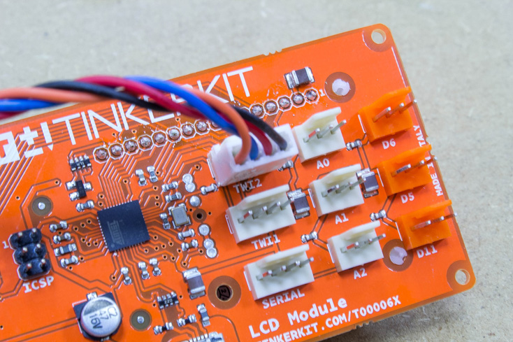
The TinkerKit LCD module also supports TWI connections. TWI stands for “Two-Wire Interface” and it’s another way to call the I2C bus technology. Basically it allows to connect multiple devices in series. This means that you can hook a large number of LCD screens, connecting them “in-line” using the two TWI ports, one for input and one for output. One of them must be the master (or you can use a TInkerKit! shield), while the others must run the TWI firmware. The TWI port has four pins, that’s why we need the 4-pin jumper wire (Molex KK 2.54mm) cable to connect them.
Verify Requirement
First of all let’s connect two modules, then we move to the code. We need the TKLCD library that you can download from the link provided.
Between the examples of the TKLCD library, there is one that is called TwiFirmware. We have to load it into one of or our LCD modules, the other module doesn’t need a firmware.
Example Code
Now we have to declare our LCDs. One is a regular TKLCD_Local, while the TWI, it’s a TKLCD_Twi
TKLCD_Local local;
TKLCD_Twi twi;
Then in the setup we initialize them normally
local.begin();
twi.begin();
After this we can use them in the loop as a normal TKLCD, let’s try to write something on them:
local.print("Hi TWI");
delay(2000);
local.clear();

twi.println("Hi Local");
delay(2000);
twi.clear();
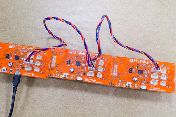
LCD Module in TWI Chain
Ok, that was rather easy, but the cool thing about TWI is that you can connect as much modules as you want. Now we try to connect three LCD modules. One will be the local master and the other two are TWI slaves. We have to load them with the TWI firmware.
If we have more than one TWI, in order to understand which one we are controlling we need to define a different address for each. Let’s open the TwiFirmware example in the TKLCD library and then, at line 88, there’s this command:
#define MATRIX_I2CADDR 0x33 // change this in order to communicate with another LCD
Every TWI module has an address that is defined in this line of the firmware program. By default it’s 0x33 but we can change it. If we have more than one module we have to define a different address for each module. Now we set one address to 0x33 and the other to 0x44, then we upload them.
Now all we have to do is program the master module. We don’t have to change barely anything from our program, we still have to declare just one TWI, but in the loop we have to set a different address everytime that we want to change the target TWI LCD. This is done using lcd.setActiveAddress(NEW_ADDRESS).
Here what we do is writing on the three screens in sequence:
local.print("I'm a local");
delay(2000);
local.clear();

twi.setActiveAddress(0x33);
twi.println("I'm TWI 0x33");
delay(2000);
twi.clear();

twi.setActiveAddress(0x44);
twi.println("I'm TWI 0x44");
delay(2000);
twi.clear();
By changing addresses, you can connect a large array of TWI devices.