Specifications
Functional Requirements
The four main functions of the Wireless Tool includes:
- Packet Monitor: The packet monitor enables the reception and surveillance of packets on a selected channel. Utilizing the ESP32's Wi-Fi capabilities, the Packet Monitoring feature captures and analyzes wireless packets in promiscuous mode, allowing it to observe all nearby Wi-Fi traffic. The collected data is then displayed in real-time on the TFT LCD screen.
- Wi-Fi Scanner: The Wi-Fi Scanning function identifies and lists nearby access points. By leveraging the ESP32's scanning capabilities, it retrieves information about SSIDs, signal strengths, channels, and security protocols. This valuable data is then presented to the user for selecting a network.
- Beacon Spammer: The spammer allows the user to select a desired channel to create and spam fake Wi-Fi access points. This involves crafting and broadcasting false beacon frames. This feature is intended for educational purposes, helping users understand how networks announce their presence.
- Deauthentication Detector: Implements de-authentication detection by monitoring the network for deauth packets. Scan all channels for any deauthentication attacks and display the number of detected packets for each channel. When an attack is detected, trigger the buzzer and LED to alert the user.
Performance Requirements
The performance requirements for the system are centered around ensuring efficient and responsive operation utilizing the ESP32S development board. The system must support real-time processing and display of data on the TFT screen, ensuring that updates are smooth and without noticeable delay. The ESP32S should handle multiple input signals from push buttons, ensuring accurate and immediate response to user interactions. Additionally, the system must maintain stable Wi-Fi connectivity for tasks involving network monitoring and packet analysis, leveraging the ESP32S’s dual-core processing capabilities to manage these tasks concurrently without performance degradation. Power consumption should be optimized to support powering from a fixed DC source (discussed in the next section). Overall, the system must balance processing efficiency, low latency in user interactions, and robust network performance to meet the intended functional requirements.
Operational Requirements
The operational requirements for the system ensure it functions reliably and effectively under various conditions. The ESP32S development board must operate within the standard voltage range, typically 3.3 or 5V, to maintain stability and performance. The system should be capable of running continuously for extended periods without overheating or failure, and this is a software optimization needed to be achieved for the hardware level. All push buttons must provide tactile and responsive feedback, with a debounce mechanism implemented to prevent erroneous multiple detections. The debouncer may be designed differently depending on the actual application (breadboard, SMD, etc). The TFT screen should deliver clear and legible displays in various lighting conditions, with sufficient brightness and contrast levels. The system must support firmware updates to allow for easy maintenance and feature enhancements. Additionally, the Wi-Fi module must reliably connect and stay connected to networks under varying signal strengths, handling packet monitoring and data transmission tasks effectively. Overall, the system should be user-friendly, durable, and capable of consistent performance in diverse operational environments.
Tech Stack
- Project tracking tool: Jira
- Hardware:
- ESP32 development module by NodeMCU or any equivalence
- 1.8” TFT screen
- Push-buttons
- Electrolytic capacitors
- Jumper wires
- RGB LED module
- Software:
- Arduino IDE
- Adafruit libraries listed in the source codes
- TFT image converter
Bill of Material
| Description | Properties | Quantity | Image |
|---|---|---|---|
| ESP32 Eval Board | 3.3V module | 1 | 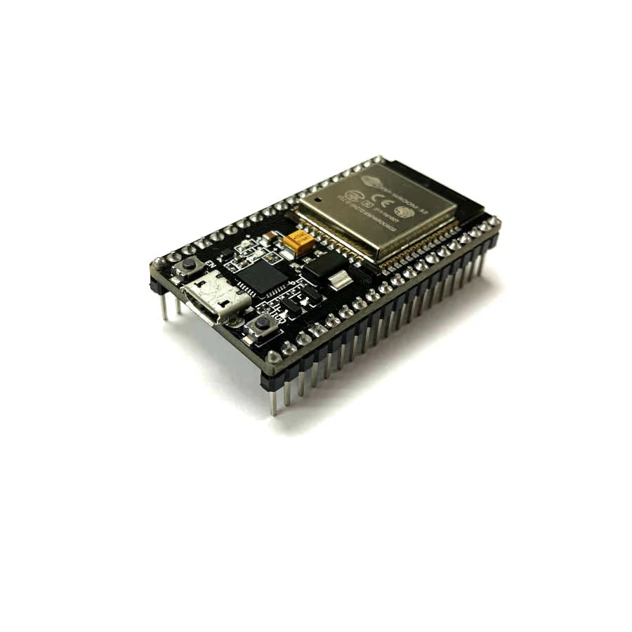 |
| 1.8” TFT LCD | Coloured 5V module | 1 | 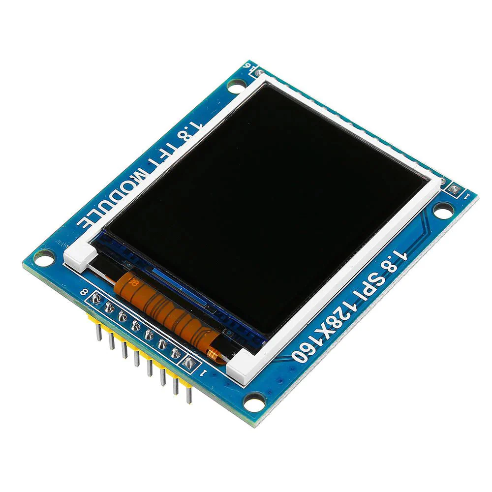 |
| Bread board | Standard | 2 | 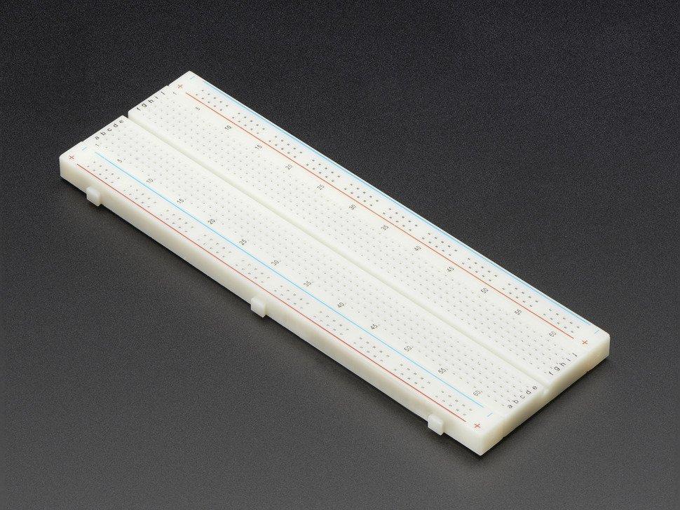 |
| RGB LED module | Tri-colour | 1 | 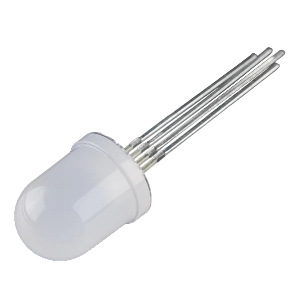 |
| Tactile Push Button | Standard | 5 |  |
| Wires | Connections wiring | Many | 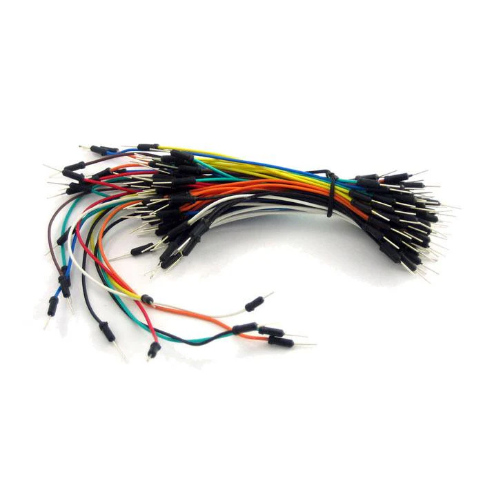 |
| Capacitor #1 | 3.3uF electrolytic | 5 | 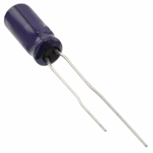 |
| Capacitor #2 | 10uF electrolytic | 2 |  |
| Micro USB Cable | Micro-USB | 1 | 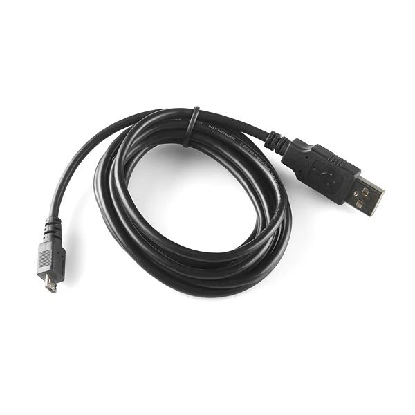 |
The proposed BoM is for constructing a minimal viable product in a timely manner. The RGB LED module is essentially an added feature which can act as a signaling device that prompts the user for designated events. For example, it is feasible to write an interrupt service routine for making the LED blink at certain event(s). This implementation will be left to the readers for further investigation, and please also mind the possibility of needing to add a current-limiting resistor for the LED module.